System Tab
EasyPower's customizable options are set up under Tools > Options.
Select the System tab of the Options dialog box to set system parameters.
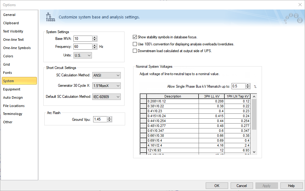
Figure 1: System Tab of Options Dialog Box
| Option | Description |
|---|---|
|
System Settings These fields are active in the Database Edit focus only. |
|
|
Base (MVA) |
The base MVA of the system your one-line represents. |
| Frequency |
The frequency of the system your one-line represents. This number is used for some of the database dialog box Calculate buttons. Make sure it is correct before you build your one-line. |
| Units |
Select U.S. or Metric, depending on your application. |
|
Short Circuit Settings |
|
| SC Calculation Method |
If your EasyPower license includes both ANSI and IEC, you can select either the ANSI or IEC-60909 short circuit method. The IEC option is named GB/T 15544 if your computer's locale is set to use Chinese. If the calculation method is set to IEC or GB/T, you can select the short circuit settings in SC Options on the Control tab. See Control Tab (IEC) for more information. The SC Calculation Method must be set to ANSI to run the Arc Flash Scenario Comparison Report. Both ANSI and IEC (GB/T) are supported for the Equipment Duty Scenario Comparison Report. |
|
Generator 30 Cycle X |
The 30 cycle reactance for a generator can be selected as 1.5x momentary reactance (1.5*MomX, the default), or the transient reactance (X’dv). This option only applies to ANSI. |
|
Default SC Calculation Method |
You can set the default short circuit calculation method for new one-lines. This only affects new one-lines. |
|
Arc Flash Ground Vpu |
In arc flash hazard calculations, the program determines that a bus is effectively grounded if the average voltage per unit for B and C phases during a line-to-ground fault on A phase is less than the value specified in this field. This option is only applicable to the IEEE 1584-2002 arc flash calculation method. The IEEE 1584-2018 method no longer includes grounding in its calculations. |
|
Show stability symbols in database focus |
Equipment such as motors and generators with stability data have different symbols in the Dynamic Stability focus. These symbols can also be made to appear in the Database Edit focus with this check box selected. |
|
Use 100% convention for displaying analysis overloads/overduties |
Displays the calculated duty or loading of equipment as a percentage of the rating. For example, if a cable has a rating of 100A and the load current is 95A, then the cable overloading is displayed on the one-line as 95%. Without this option enabled, the display is -5%. |
|
Downstream load calculated at output side of UPS |
By default, the downstream load calculations of the bus on the input side of a UPS matches the UPS kVA rating. Select this check box if you want to use the downstream load calculations from the bus on the output side of the UPS and apply it at the bus on the input side of the UPS. |
|
Nominal System Voltages |
|
|
Allow Single Phase Bus kV Mismatch up to: |
Specify the percentage tolerance you want to allow when a three-phase and one-phase line-to-neutal circuit are connected but the bus kV between the two circuits does not match. Enter a range between 0 and 1%. Standard voltages in the industry are often rounded off to some significant digits. The ratio of standard 3PH Line-to-line voltage to standard LN voltage may not be exactly the sqrt(3). Note: This option is included as part of the default settings that are modified if you reset the table as described below. |
|
(Nominal System Voltage Table) |
Use this table to enable the single-phase line-to-neutral voltage to take the nominal voltage rather than the calculated 1/sqrt(3) voltage when single-phase equipment is connected to three-phase equipment. You can modify this table by manually changing the values. The table is stored within the one-line file. Additional functions are available by right-clicking on the table. These include:
Note: If you reset the table, it also resets the Allow Single Phase Bus kV Mismatch up to percentage value. |