MCC - Summary Tab
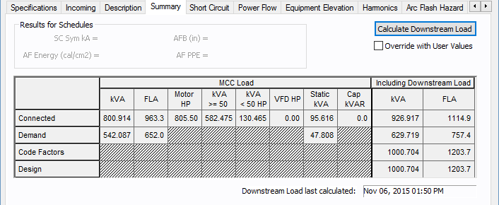
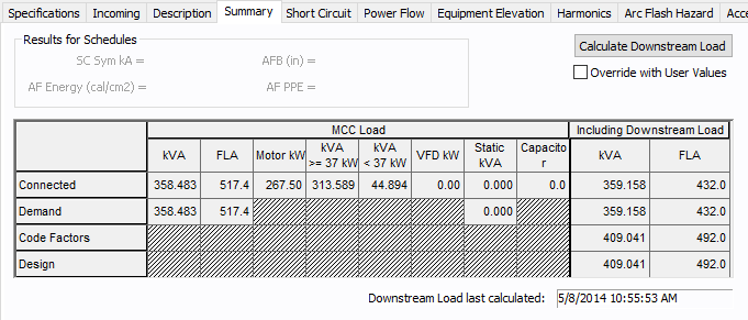
The Summary tab of MCC Data dialog box provides the total load on the MCC and the load that must be used in designing.

Figure 1: Summary Tab (U.S. Units)

Figure 2: Summary Tab (Metric Units)
| Option | Description |
|---|---|
|
Calculate Downstream Load |
Calculates the total load on the MCC, taking into account the connected load, demand factors, and NEC code factors. Single-Phase Load Calculations: Load calculations for 1PH equipment follow the conventional load calculation method similar to 3PH systems. TThe current value in Amps is obtained from the average connected kVA. For right-most column in the Summary tab (Including Downstream Loads), the apparent power (VA or kVA) of individual downstream loads is summed up first for each energized (hot or live) current carrying conductor. The respective load current is calculated from the voltage for the line of circuit. For each branch circuit tapped off at the distribution point, the program keeps track of the phase connection type. For example, phase connection for 1PH branches could be AN, BN, CN, AB, BC or CA. During load calculations, downstream load values are applied to the correct phases at the upstream distribution point. The results are displayed under the Downstream Load column. |
|
Override with User Values |
This check box enables you to enter data in the Total Downstream Load – kVA column. |
Spreadsheet
The spreadsheet has two sections – MCC Load and Including Downstream Load.
| Option | Description |
|---|---|
|
MCC Load This spreadsheet section provides the summary of the loads fed by the feeders of the MCC. The loads from the sub-MCC and sub-panels are not included in this section. |
|
|
Total kVA |
This is the aggregate load. |
|
Total FLA |
Total load in amps. |
|
Motor HP |
The total HP for the items with "On" in the Status column of the Description section. |
|
Motor kVA >= 50 HP Motor kVA >= 37 kW |
The total KVA for connected items equal to or greater than 50HP (U.S. units) or 37 kW (metric units). |
|
Motor kVA < 50 HP Motor kVA < 37 kW |
The total KVA for connected items greater than 50HP (U.S. units) or 37 kW (metric units). |
|
VFD HP or kW |
Variable frequency drive HP (U.S. units) or kW (metric units). |
|
Static kVA |
Total kVA of the loads. |
|
Capacitor kVAR |
Total kVARs of all the capacitors |
| (Calculations) | |
|
Connected |
Connected kVA = [(SkW)2 + (SkVAR)2]1/2 |
|
Demand |
Demand kVA = [S(kW * DF)2 + S(kVAR * DF)2] ½ Where DF is the individual demand factor of each MCC circuit. |
|
Code Factors |
Code Factors kVA = [(kWL + SkW)2 + (kVARL + SkVAR)2]1/2 Where, kWL = Code Mult Factor * kW for largest motor in MCC. KVARL = Code Mult Factor * kVAR for largest motor in MCC. kW and kVAR are for the rest of the loads. The code multiplying factor is specified in Tools > Options > Equipment. |
|
Design |
Design kVA = Code Factors kVA * Design Factor The Design Factor is specified in Tools > Options > Equipment. |
|
Including Downstream Load This provides the sum of the loads fed by feeders inside the MCC and the sub-MCC and sub-panels. |
|
|
kVA |
Total kVA load calculated. You can enter your own values in these fields by selecting the check box for Override with User Values. |
|
FLA |
Total FLA load calculated. You can enter your own values in these fields by selecting the check box for Override with User Values. |
More Information
- Motor Control Center (MCC) Data
- Database Dialog Box Toolbar
- MCC - Connection Information
- MCC - Specifications Tab
- MCC - Incoming Tab
- MCC - Description Tab
- MCC - Short Circuit Tab
- MCC - Power Flow Tab
- MCC - Equipment Elevation Tab
- MCC - Harmonics Tab
- MCC - Arc Flash Hazard Tab
- MCC - Accessories Tab
- MCC - Reliability Tab
- MCC - Location Tab
- MCC - Comments Tab
- MCC - Hyperlinks Tab
- MCC - Collected Data Tab
- MCC - Media Gallery Tab
