Relay - Settings Tab
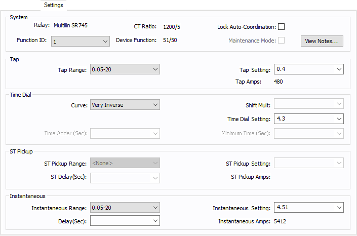
Figure 1: Settings Tab
| Option | Description |
|---|---|
|
Shows the Function ID, Device Function name and CT Ratio of the device function selected. The values entered in the remaining sections of the Specifications tab are for the device function shown in Function ID field. |
|
|
Lock AC |
Check box to lock auto coordination. Any device function with the check box selected will not auto coordinate. |
|
Maintenance Mode |
Specifies whether the maintenance mode instantaneous trip switch is on or off for the device function. Some relays might not have a maintenance mode trip switch. When the check box is selected, the TCC can be plotted and arc flash calculation will include the trip time. |
| Click to view notes recorded in the library for the device. Information may include data sheets or manufacturer's information for the device or assumptions needed to model the device. | |
|
The tap settings or the pickup settings for time-overcurrent function. The name may be relay specific, such as Pickup, I>, and so on. |
|
|
The range of tap settings which is applicable to the relay. Some relays might have only one range of tap settings, but relays of the same model might come with different tap ranges. In such cases, all possible ranges might be included in a relay type in the library. |
|
|
Tap Setting |
Depending upon the tap range selected, the available tap choices are listed here. The selected tap sets the pickup current. |
|
The pickup current in the one-line circuit is displayed below Tap Setting. |
|
|
Selection of type of time-overcurrent curve, and the time dial (delay). This section is name as Time Dial in the library by default. In some cases, for example motor protection relays, they may be called by other names such as Thermal Overload. |
|
|
Curve |
Provides a list of available curves for the device function. |
|
Time Dial Setting |
Provides the range of time delays that can be set for the curve selected. Some relays call this time multiplier. In some recloser relays, the time dial (or time multiplier) also affects the instantaneous time delay. |
|
Shift Multiplier shifts the curve in the vertical direction. This is functionally similar to the time dial and is available in only some relays. |
|
|
Time Adder |
Some relays (mostly recloser relays) have additional time delays to the regular trip curves. This field increases the trip time by the selected value of time in seconds or cycles. |
|
Minimum Time |
Some relays (mostly recloser relays) have a minimum time setting. The time-overcurrent function never trips faster than the specified time. In a TCC plot, the curve becomes flat at this time even if the inverse time curve is programmed to trip at faster times. |
|
The instantaneous pickup range and setting, and time delay are entered in this section. Some relays may have different names for this section, such as Short Circuit Instantaneous, Locked Rotor Instantaneous, and so on. For relays that have both high and low instantaneous settings, it may be necessary to use two device functions. |
|
|
Instantaneous Range |
Provides a list of ranges of instantaneous pickup values applicable to the relay. The Instantaneous settings available depend on the Instantaneous Range selected. |
|
Instantaneous Setting |
The instantaneous pickup setting. |
|
Instantaneous Amps |
The instantaneous pickup current in the one-line circuit is displayed below Tap Setting. |
|
Instantaneous Delay |
Time delay for instantaneous trip. |
|
ST Pickup |
Relays with three stage overcurrent relays have the second instantaneous trip with time delay (also called short time in some relays). |
|
ST Pickup Range |
Provides a list of ranges of short time or second instantaneous pickup values applicable to the relay. The ST Pickup settings available depend on the ST Pickup Range selected. |
|
ST Pickup Setting |
The second instantaneous or shot time pickup setting. |
|
ST Pickup Amps |
The instantaneous pickup current in the one-line circuit is displayed below Tap Setting. |
|
ST Delay |
Time delay for short time trip. |
Some relays have settings and time current curves just like the low voltage breaker solid state trip devices. The common type is direct action trip (DAT) units found in some medium voltage breakers. The settings tab for these relays has a slightly different layout as described below.
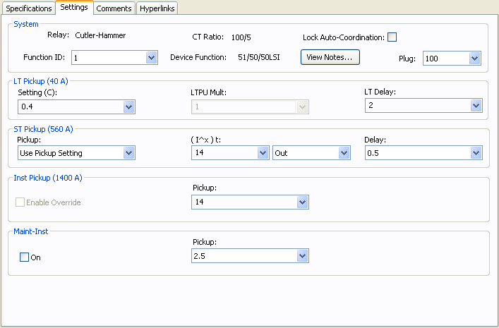
Figure 2: Relay Data – Settings Dialog Box for DAT
| Option | Description |
|---|---|
|
Plug |
Select the rating plug on the trip unit. The sensor is equal to the CT primary amps. |
|
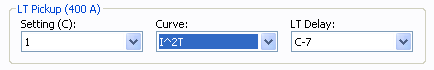
The long time pickup and delay are selected in this section. The pickup calculation depends on the device selected. It may include LTPU Mult, but it will include Setting (C). After the settings are selected, the actual pickup in amperes appears in parentheses. |
|
|
Setting (C) |
The long time pickup current setting below which the device will not trip. This is a fraction of the sensor or plug/tap amps. For some trip units LTPU multiple may also be required to set the pickup current. |
|
Multiple of Setting (C), which can be adjusted to “fine-tune” the long time pickup setting. Some trip units may not have this feature. |
|
|
Curve |
Some relays may have multiple LT delay curves to choose from. This field enables you to choose the curve shape.
|
|
Long time delay setting to select the delay band. |
|
|
Short time pickup and delay settings. This section is applicable to only devices with short time trip. After the settings are selected, the actual pickup in amperes appears in parentheses. |
|
|
Pickup |
The short time pickup current setting below which the device will not trip for short time trip. The short time pickup setting may be a multiple of long time pickup, sensor rating, or plug. |
|
To select shape and slope of delay short time band. When you select In, the (I^x)t function is enabled. The delay band has a slope of minus “x”. When you select Out, the (I^x)t function is disabled, and the short time delay is independent of the current. For some new circuit breakers, the (I^x)t delay may be adjustable. In such case, the choices available are the various possible delay settings. |
|
|
Delay |
Short time delay setting to select the delay band. |
|
Nominal instantaneous trip amps, multiple, or pickup setting. When you highlight or select a choice, the corresponding trip amps appear in parenthesis. |
|
|
Pickup |
The instantaneous trip pickup setting. |
|
Selecting Enable Override disables tripping based on the pickup setting. The device trips at an override value that depends on the device style. This feature may or may not be applicable to the device selected. |
|
|
Maint-Inst |
This is the additional instantaneous setting used during maintenance to lower the arc flash hazard. The name of this section may be manufacturer specific such as ARMS, Maint Mode, and so on. |
|
On |
Select this check box to indicate the maintenance switch is on. In analysis focus, you can select the breakers and with a right mouse click you can toggle the maintenance mode switch on or off. |
|
Pickup |
Setting for maintenance mode trip. |