EasyPower 10.4 Release Details
This topic describes new EasyPower features and enhancements, as well as bug fixes that are included in the release.
Service Packs: For information on the latest service packs for this release, see 10.4 SP2 Release Notes.
Note: New release features often include changes to the database. This may affect what you see in the Database Browser and also what is included when you export data into CSV files. If your existing work processes rely on information from the database, be sure to review your processes after you update your software.
The release includes the following:
Single-Phase Modeling
EasyPower now supports single-phase modeling on the one-line. This includes:
- Single-phase tap from three-phase equipment using a line-to-line or line-to-neutral connection.
- Single-phase tap from single-phase three-wire equipment using a line-to-line or line-to-neutral connection (for example, 120/240V).
- Single-phase short circuit calculations including reports and equipment duty analysis.
- Single-phase arc-flash calculations including reports and labels.
- Single-phase protective device coordination and TCC plots.
- Single-phase design load calculations.
These features and more are described below. For additional information, refer to Single-Phase Modeling.
Phase Selection When Adding Items to the One-line
The Equipment Palette and the Insert tab have options to insert three-phase (3PH) or single-phase (1PH) items onto the one-line. Three-phase is the default selection.
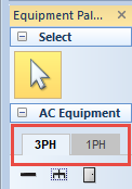
Figure 1: Phase Selection on the Equipment Palette
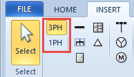
Figure 2: Phase Selection on the Insert Tab
Select the phase you want before you add the item to the one-line, from three-phase (3PH) or single-phase (1PH). You can change your selection later if needed, but this ensures the items are created with the desired phase.
The program displays 1PH next to the pointer as you drag an item onto the one-line to indicate that a single-phase item is selected.

Figure 3: Single Phase Indicator Next to Pointer
Phase Connector Symbols on the One-line
The phase connector symbol appears as two diagonal slash marks below the point where the single-phase tap is made.
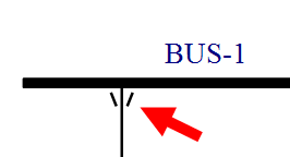
Figure 4: Phase Connector Symbol
You can turn the phase connector symbol visibility on or off globally in Tools > Options > One-line Symbols. See One-line Symbols Tab for more information.
The phase connector symbol is visible on one-lines, drawings, TCCs, print, and DXF outputs.
Tip: Hover the mouse pointer over the phase connector symbol to display the connection type in a tool tip.
Setting the Nominal System Voltage
Line-to-neutral voltage of three-phase distribution systems is equal to the base kV divided by √3. This table in Options on the System tab can be used to adjust the single-phase tap voltage to a nominal value. If the base kV of the three-phase equipment is not identified in this table, the line-to-neutral tap voltage of single-phase equipment defaults to the base kV divided by √3. An additional setting is provided to allow for a voltage mismatch tolerance when connecting single-phase equipment to three-phase systems.
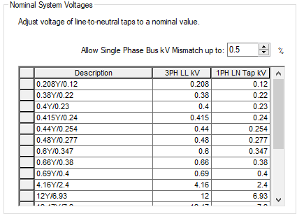
Figure 5: Nominal System Voltage Table
Note: If you enter a line-to-line voltage on the one-line that is not specified in the table, EasyPower calculates the line-to-neutral voltage using the √3 difference. Similarly, if you enter a line-to-neutral voltage on the one-line that is not specified in the table, EasyPower calculates the line-to-line voltage using the √3 difference.
Equipment Defaults
You can specify the equipment defaults including the phase of the equipment by selecting the item from the Equipment Defaults menu under the appropriate phase, and then entering the default data you want to use. This enables you to have different default settings for three-phase and single-phase equipment.
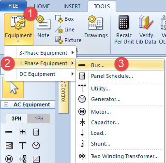
Figure 6: Equipment Defaults
Specify Colors by Phase or Voltage Level
You can specify equipment colors based on the either the phase type or the voltage level. This is done in Tools > Options > Colors.
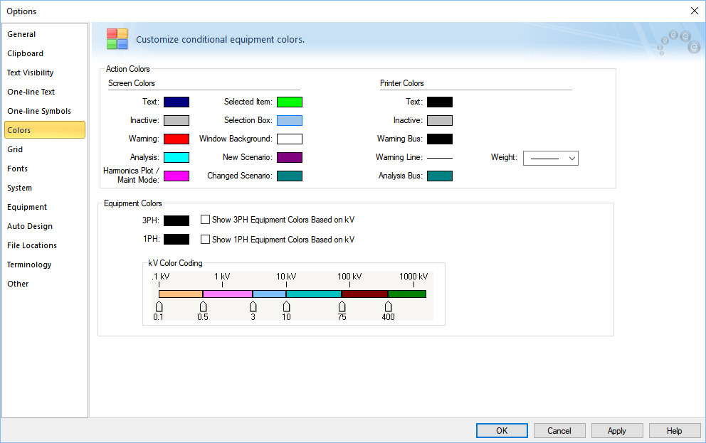
Figure 7: Colors Tab in System Options
You can select a specify a color for all three-phase (3PH) or single-phase (1PH) equipment on the one-line. You can also select the Show Equipment Colors Based on kV check box for each phase type to have the equipment display different colors based on voltage. You can do this for three-phase equipment, single-phase equipment, or both.
Center Tap Transformer
You can use the Center tap connection check box to make a 1PH transformer 1PH-3W at the secondary side. The transformer impedance of the LN connection is 1.5R and 1.2X when compared to the impedance of LL connection.
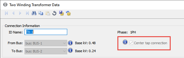
Figure 8: Center Tap Connection Check Box Selected on a Single-Phase Transformer
Same as Phase Option for Neutral Wire
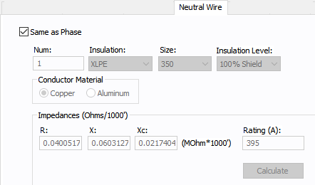
Figure 9: Same as Phase Option for Neutral Wire
You can set the cable specifications for the neutral wire to be the same as the phase or you can modify them individually.
- If you select the Same as Phase check box, the cable values are copied from the Specifications 1 tab to the Neutral tab.
- If you clear the Same as Phase check box, you can enter the cable specifications for the neutral wire. If the Number of Neutral Wires is set to 0, the program uses the impedance of the phase cable.
Single-Phase Panel Templates
There are new panel schedule templates for 2- and 3-wire panel schedules. You can set the file location for these files globally in the system Options on the File Locations tab or for individual one-lines in the File Properties on the Properties tab.
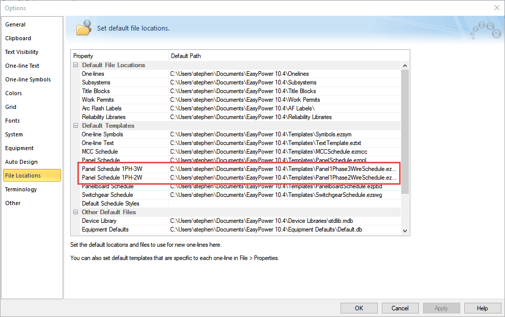
Figure 10: File Locations Tab
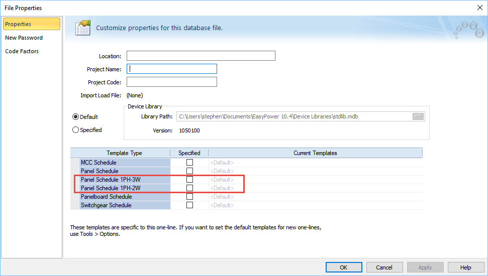
Figure 11: File Properties Tab
The panel schedule templates have been modified to properly display phase information for single-phase equipment.
Panel Schedule 1PH-3W Templates
The template for 1PH-3W is similar to the standard panel template, except:
- The grid has only 2 columns for load values and the columns are labeled L1 and L2. The columns show loads from phase A and B, B and C, or A and C depending on the phase of the panel.
- The rows are labeled 1,3,5,7, and so on for the left side and 2,4,6,8, and so on for the right side. If you enter load data in the standard diagonal arrangement on the diagonal, this means that for an AB phase type, 1=A, 2=B, 3=A, 4=B, and so on.
- The Code Factors table has only two columns for the loads and the columns are labeled VA(L1) and VA(L2). The columns show loads from phases A and B, B and C, or A and C, depending on the phase of the panel.
Note: The 1PH-3W template is also used for 1PH-2W panels that display 2 columns.
Panel Schedule 1PH-2W Templates
The template for 1PH-2W is similar to the standard panel template, except:
- The grid has only 1 column for load values and the column is labeled Load. The column shows loads from A or B or C depending on the phase type of the panel.
- The Code Factors table has only one column for the load. The column is labeled VA and shows loads from A or B or C, depending on the phase type of the panel.
Panel Schedule Variables for Single-Phase Templates
There are new panel schedule variables that support single-phase templates. The new variables use the phase number instead of the phase name and are as follows:
- %Phase1Total%
- %Phase2Total%
- %Phase3Total%
Note: For 3-phase panel schedule templates, these new variables replace %PhaseATotal%, %PhaseBTotal%, and %PhaseCTotal%. However, the old variables remain available in the software to support older templates.
In addition to the above, the variable %Voltage% has different behavior depending on the phase and service of the panel.
- If the panel is 3PH (regardless of the service), the variable displays both the base kV and LG voltage. The LG voltage is the base kV divided by SQRT3.
- If the panel is 1PH and the service is 1PH-3W, the variable displays both the base kV and LG. The LG voltage is the base kV divided by 2.
- If the panel is 1PH and the service is 1PH-2W, the displays only the base kV.
Equipment Duty for Single-Phase Devices
While performing equipment duty calculations for 1-phase devices at a 3-phase bus, you can choose to use the fault types specific to faults within the outgoing 1-phase circuit or the types of faults available for 3-phase buses.
Similarly, while performing equipment duty calculations for 1-phase devices at a 1PH-3W bus, you can choose to use the fault types specific to faults within the outgoing 1-phase circuit or the fault types available for 1PH-3W buses.
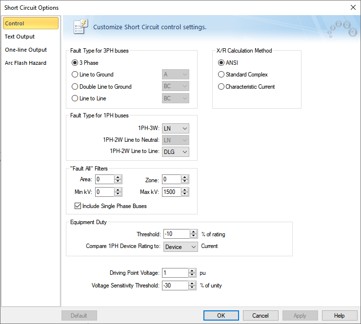
Figure 12: Short Circuit Options - Control Tab
In the Short Circuit Options dialog box on the Control tab, use the Compare 1PH Device Rating option to select which current you want to use. You can choose from the following:
- Device: This applies the 1-phase fault type and compares the device ratings with the fault currents through the 1-phase devices (see the options under Fault Type for 1PH buses). This applies to protective devices that appear in the one-line view. Devices within panels and MCCs are compared to the bus current.
- For 1PH-3W equipment you can choose between line-to-neutral fault (LN) and line-to-line fault (LL).
- For 1PH-2W line-to-neutral connected equipment, the fault type is line-to-neutral. This applies for equipment fed from 3-phase or 1PH-3W services.
- For 1PH-2W line-to-line connected equipment that is fed by a 3-phase system, you can choose between a double-line-to-ground (DLG) fault and a line-to-line (LL) fault. For line-to-line connected equipment fed from a 1PH-3W system, only line-to-line faults are applied.
- Bus: This choice applies the types of fault available at the bus. 3-phase buses can have the faults 3-phase, single-line-to-ground, double-line-to-ground, or line-to-line. You can choose the fault type for 3-phase buses from the Short Circuit Options or from the short circuit menu. 1PH-3W buses can have a line-to-ground fault or a line-to-line fault. For 1PH-3W, you can choose the fault type only from within this dialog box.
The following 1-phase fault types are available:
Note: For circuits fed by a 1PH-3W service, the fault to ground can be higher than the line-to-line fault.
Phase Variable for Arc Flash Labels
There is a new variable you can use in your arc flash label designs to indicate the number of phases.
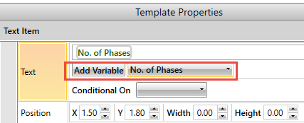
Figure 13: Number of Phases Variable for Arc Flash Labels
Number of Phases Variable for Custom Work Permits
There is a new variable for use on work permits named {{NOPH}} that you can add to custom work permit templates to display the number of phases for a bus.
Default Fault Types for Buses
In the Short Circuit Options on the Control tab, you can specify the default phases to fault in each fault type for 3-phase and single-phase buses.
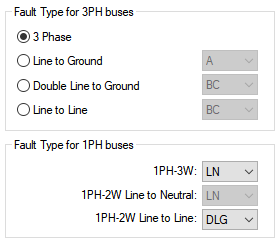
Figure 14: Fault Type Options in Short Circuit
Short Circuit Report Options
There is a new option to include or exclude information about the number of phases in short circuit reports.
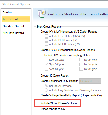
Figure 15: Include Number of Phases Column in Short Circuit Reports
Report Changes to Support Single Phase
There is a new column on the Equipment Duty Report to display the number of phases when the option to display the number of phases is selected. The report header now includes fault type information for both three-phase and single-phase buses.
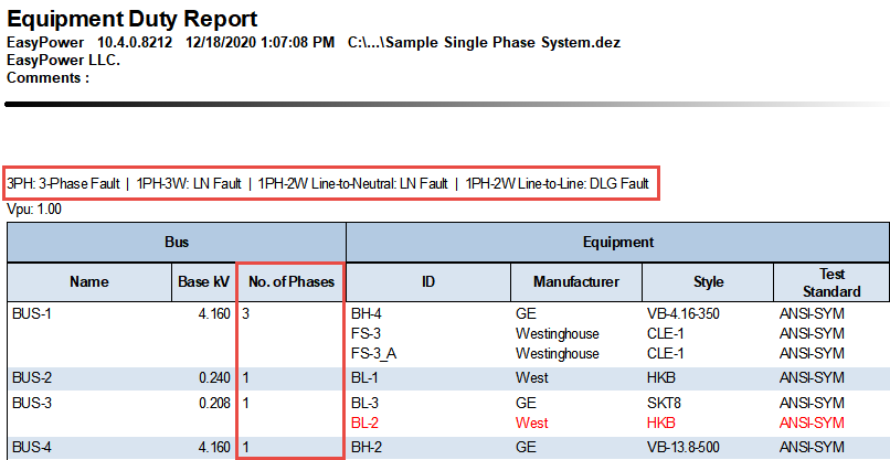
Figure 16: Equipment Duty Report with Number of Phases
Similarly, the Arc Flash Hazard Report also includes a column for the number of phases.
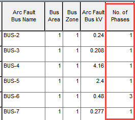
Figure 17: Arc Flash Hazard Report with Number of Phases
If the option is selected to include the number of phases on short circuit reports, the reports include a column for the number of phases, and the base kV reflects the appropriate value for the phase. This applies to both ANSI and IEC reports.
Information appears in the heading of the report to describe the fault types for three-phase and single-phase faults.
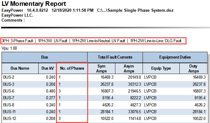
Figure 18: ANSI Short Circuit Report with Single-Phase Information
Note: If you export your report results as part of your work processes, be aware that the changes to the report could impact your process. Be sure to review any export processes to ensure they continue to work as you expect.
Voltage Mismatch Warnings
When entering an analysis focus on a one-line, the program identifies any voltage mismatches. You can ignore the warnings and continue or view the report. When viewing the report, you can double-click an item in the report to edit it.
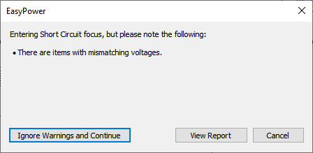
Figure 19: Voltage Mismatch Message
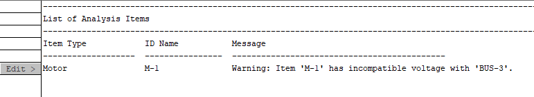
Figure 20: Voltage Mismatch Error Report
Conductor Text Block Variables
There are several new text block variables for conductors (such as cables):
- Phase Num: A calculated value of the number of phases based on the phase type.
- Phase & Neutral Num: A calculated value of the number of the Phase Num variable plus the Neutral Num variable.
- Total Phase & Neutral Number: A calculated value of the No/Ph variable multiplied by the Phase & Neutral Num variable.
Use these variables to determine the number of phase conductors in a cable run per parallel path for single-phase cables. This is useful for knowing how many wires exist per circuit.
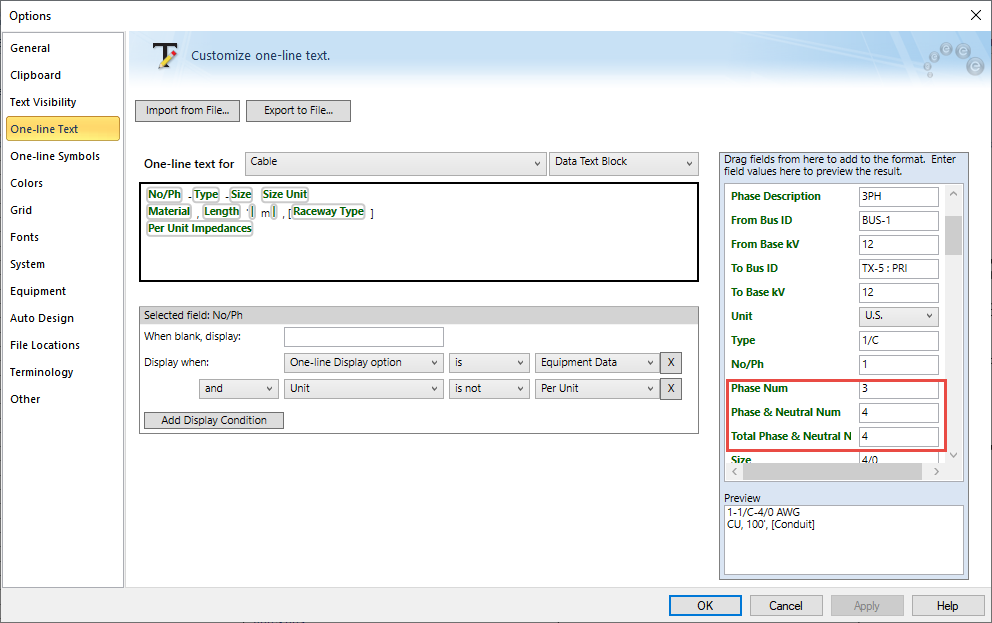
Figure 21: Conductor Text Block Variables
While we continue to support the use of the Neutral Num text block for 3-phase systems (by assigning a 0 or 3 to determine the total number of current carrying conductors), we encourage you to use the new variables to support all phase types.
TCC Scaling Based on Connection Type
There is a new check box for TCC scaling based on the connection type. This check box is available in the data dialog box of an LV breaker, fuse, relay, motor, two-winding transformer, or generator. The check box also appears on the Temporary Cable Data dialog box when you plot TCCs in the Coordination focus.
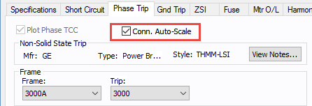
Figure 22: Connection Auto-Scale Check Box on a Low Voltage Breaker
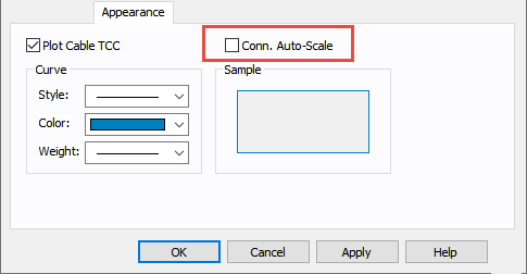
Figure 23: Connection Auto-Scale Check Box on a Cable in Coordination
When this check box is selected, the program automatically scales the TCC curves based on the phase connection type. Traditionally, for 3PH curves in a TCC, scaling the curves based on the reference voltage is adequate. If a line-to-neutral connected 1PH device is to be plotted with an upstream 3PH device, then the LN connected 1PH curve needs to be shifted by a factor of the SQRT(3) in addition to the voltage-based scaling. Similarly, if a line-to-neutral connected 1PH device is to be plotted with an upstream 1PH-3W device, then the LN connected 1PH curve needs to be shifted by a factor of the 2 in addition to the voltage-based scaling.
When the check box is not selected, scaling based on the phase connection type is not applied.
The check box status for individually stored TCC plots can be different. The default for new TCC plots is obtained from the database for the device.
Setting the Reference Bus for TCC Scaling
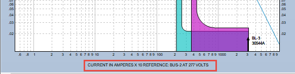
The horizontal axis of the plot has a voltage reference that includes a reference bus.
If there were only 3PH equipment in the TCC it would be sufficient to scale all equipment curves based on voltage only. When single-phase equipment is included, the phase connection type requires additional factors to be considered while overlaying the curves on a common plot.
In the one-line window of the left side of the TCC plot, you can right-click on the bus you want to use as the reference and select Set as Reference for TCC Scaling.
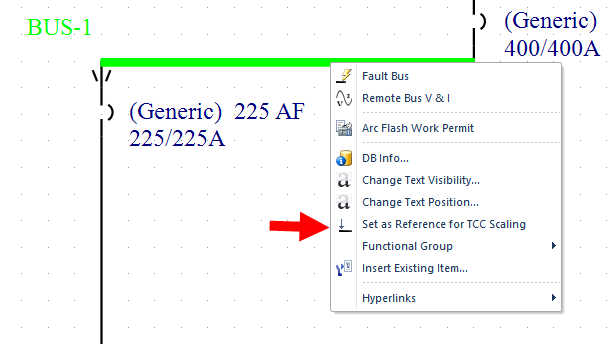
Figure 24: Set as Reference for TCC Scaling Option
This changes the reference bus and voltage and shifts the curves accordingly, as shown below.
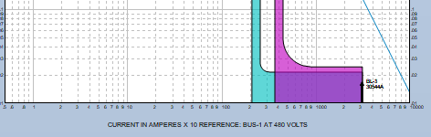
Figure 25: Horizontal Axis and TCC Scale
Support for NFPA 70E 2021
EasyPower now supports NFPA 70E 2021 in the Advanced Arc Flash Options for shock boundaries and PPE levels. The PPE tables in the device library are updated to include the 70E 2021 PPE levels.
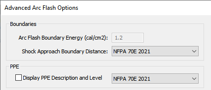
Figure 26: Advanced Arc Flash Options for NFPA 70E 2021
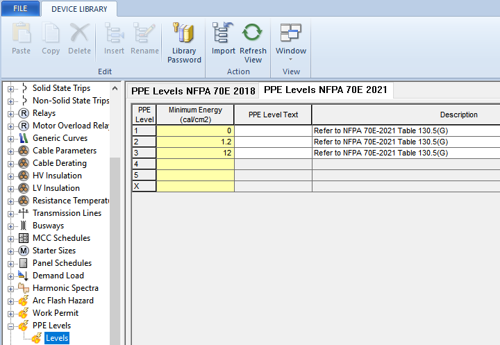
Figure 27: PPE Levels for NFPA 70E 2021 in the Device Library
The PPE Level table for 70E-2021 has been modified to a match the format of NFPA-70E table 130.5(G). The default library no longer includes the upper threshold of 40 cal/cm2 for the "Danger!" level. You need to add this if it is desired. Also, the default library does not include the PPE Category based on table 130.7(C)(15)(c). You can customize the library if needed to replicate the PPE Levels.
Revit® Integrator Updates
This release includes the following updates to the Revit Integrator:
- Support for Revit 2021.
- A new parameter for the Revit fixture families than enables you to export fixture data to EasyPower.
- When upstream distribution is modeled as a bus, the one-line displays the feeder breaker, cable, and load.
- When modeled as a panel, the panel row displays the feeder breaker, cable, and load.
- Ability to import the Revit circuit Rating data to the Trip Amps field on an LV breaker, panel main breaker, or sub-panel breakers. If the data is imported, the rating data from the import is used rather than the EasyPower library data.
- Ability to import the frame size data from the Revit circuit.
- Ability to map Demand Factor from Revit loads to panel rows in EasyPower.
- Ability to map Diversity Factor for switchgear, switchboards, and panelboard from Revit to EasyPower.
- Ability to round lengths (to the nearest foot or meter) in the Configure Revit Import dialog box.
- Ability to map Cable Type in the circuit mapping for a cable.
Find-Select Feature Improvements
The Find-Select feature includes usability improvements to make the feature easier to use and to provide additional functionality. See Selecting by an Item's ID Name (Find-Select) for more information.
Quantity Based Demand Factor
Load calculations now enable you to specify load categories for which the demand factors can vary with the number of items. You can define demand factors (code factors) based on the quantity in the Demand Load section of the library or in the File Properties under Code Factors.
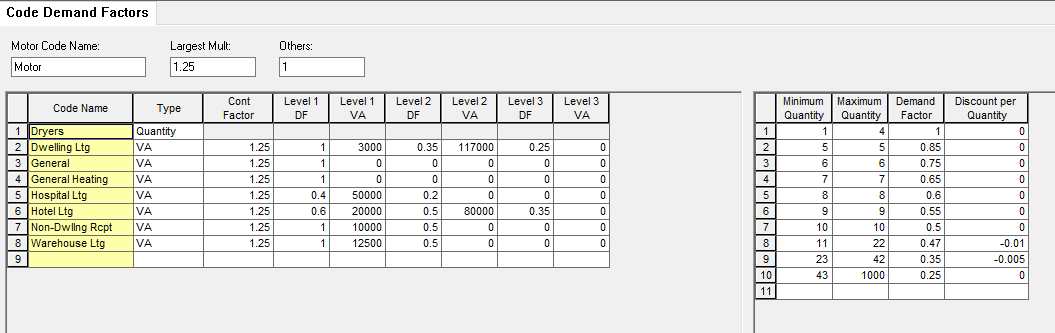
Figure 28: Code Demand Factors in the Device Library
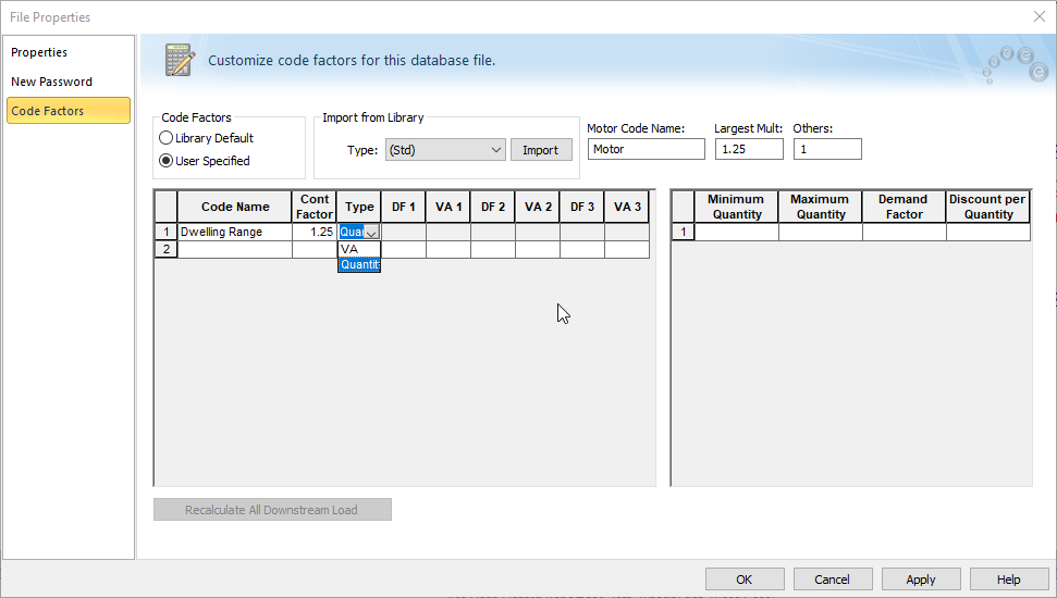
Figure 29: Specifying Code Factors in the File Properties
Custom Terminology for Phase Descriptions
There is a new Terminology tab in System Options where you can specify your own custom terminology for phase descriptions in EasyPower. The custom terminology is stored with the database file so that if other users open the file, they see the custom terms. You can save the custom terminology as the default terms, which makes them available for use in other files.
Currently, phase descriptions are the only customizable terms, but we plan to add more functionality to this feature in the future.
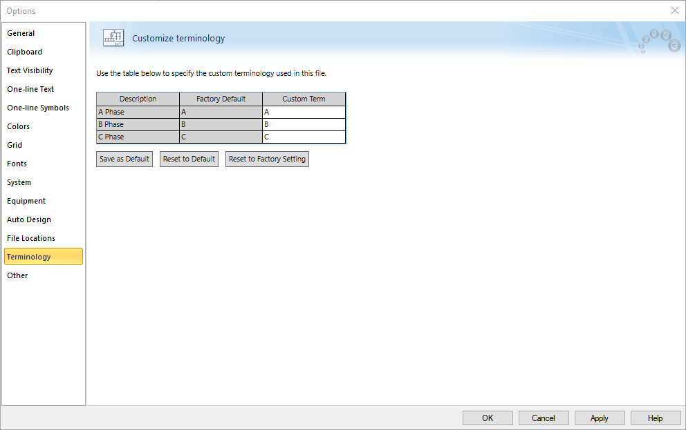
Figure 30: Terminology Tab
Data Text Block 2 Added for Buses
You can now add a second data text block for buses to the one-line text template. You can use the text editor to select which additional information you want to appear in the data text block on the one-line. The text block is blank by default.
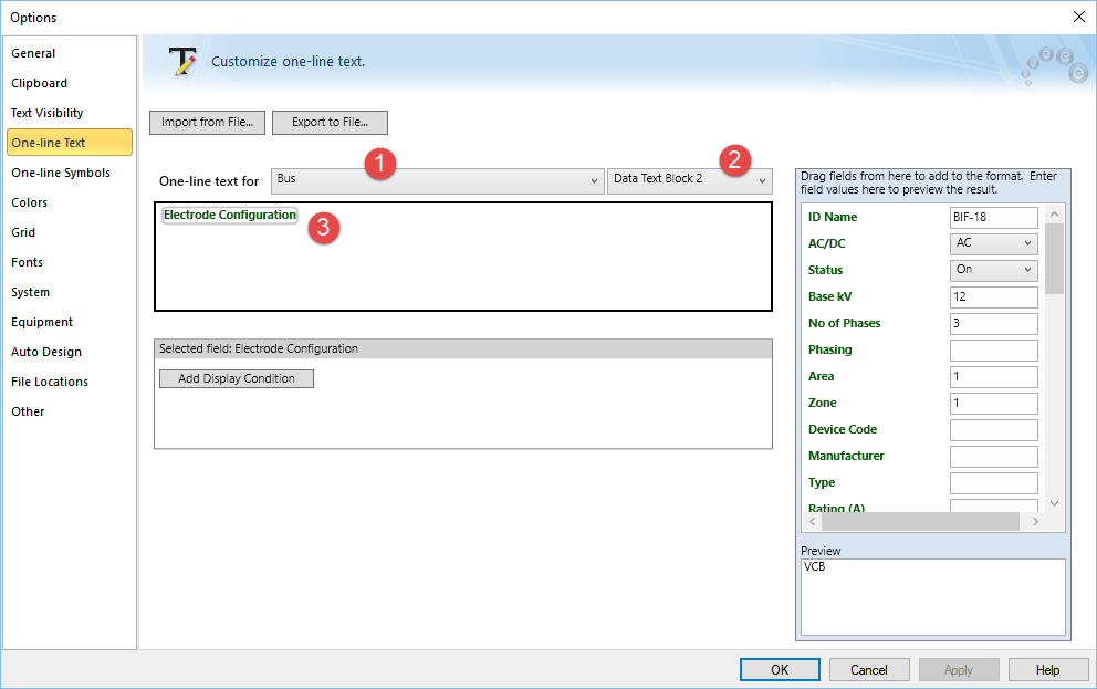
Figure 31: Creating the Contents of Data Text Block 2 for a Bus in the Text Editor
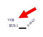
Figure 32: Data Text Block 2 on the One-line
Support for IEEE-1584-2018 in Dynamic Stability
You can now select either IEEE-1584 2018 or IEEE 1854-2002 as the arc flash standard to follow when in Dynamic Stability. The option is set in the Dynamic Stability Options dialog box on the Arc Flash tab.
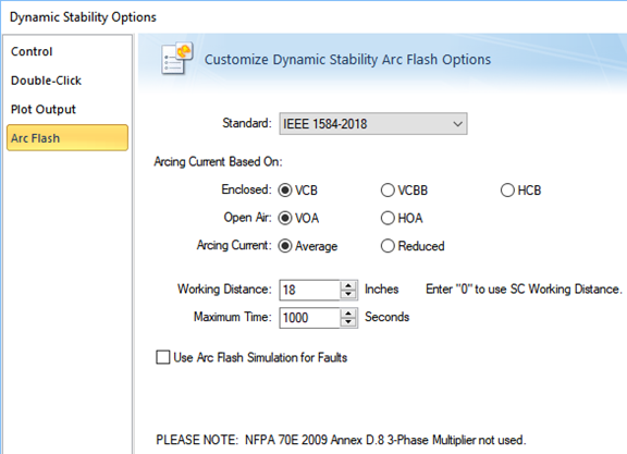
Figure 33: Dynamic Stability Options - IEEE 1584-2018 Standard Selected
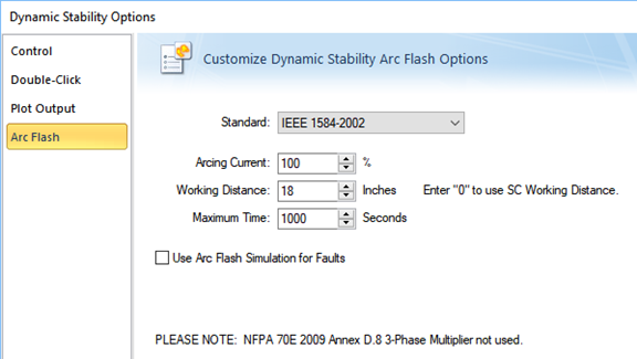
Figure 34: Dynamic Stability Options - IEEE 1584-2002 Standard Selected
Error Report Improvements
When EasyPower displays an error report (such as when you attempt to open the Short Circuit focus with incomplete data), you can now easily edit the item in one of three ways:
- Click Edit next an item in the report to open the item's data dialog box.
- Double-click on the item in the list to open the item's data dialog box.
- Right-click on the item in the report to display a context-sensitive menu that enables you to either open the data dialog box or find the item on the one-line.
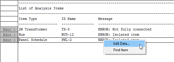
Figure 35: Context-Sensitive Menu in the Error Report
TCC Enhancements
The device library has been modified so that breakers can be modeled as follows:
- Thermal magnetic breakers can now show an additional instantaneous override curve.
- Decreasing curves are now supported for the override trip in breakers.
Custom Shortcut Keys
If you have set up custom shortcut keys, these are preserved and no longer overwritten when upgrading the EasyPower program. Customization of the Quick Access Toolbar is also preserved.
Notes in EasyPower
Notes can now contain up to 1,000 characters.
Contacting Support
There is now a link in the program to make it easier for you to contact EasyPower technical support and to provide us with important system information to help resolve issues.
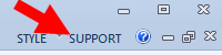
Figure 36: Support Link
When you click the link, you are given multiple support options, along with a recap of your important system and program information.
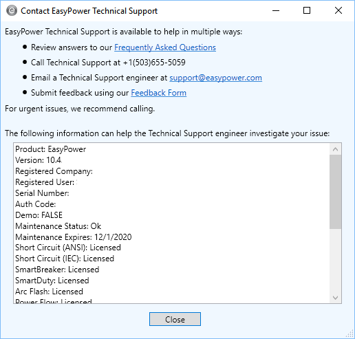
Figure 37: Contact EasyPower Technical Support Dialog Box
Bug Fixes
The following issues have been addressed in this release:
-
An internal error message is displayed repeatedly when entering an analysis focus due to corrupted information in an AFD.
-
The phase shift integrity warning message displays an unrecognizable internal ID and prevents opening the Short Circuit or Coordination focuses when the Verify phase-shifting integrity of system check box is selected in Options on the General tab.
-
When multiple buses are faulted, the Peak IEC short circuit currents in contributing branches are reported incorrectly.
-
If a motor HP includes a decimal, the TCC plot for the motor may display a different HP due to a rounding error.
-
A TCC note shows in the TCC plot without the corresponding TCC curve when the TCC clipping is turned on.
-
After a TCC plot is saved in which the transformer kVA is less than the lower limit for ANSI or IEC, reopening the TCC plot does not display a warning, and the transformer curve is not shown.
-
The trip amps on the TCC Coordination report display a different value than the equipment data.
-
When plotting a breaker that is missing information in the device library, the EasyPower program terminates instead of displaying a warning message.
-
After deleting a breaker in a TCC plot, the deleted breaker’s curve remains visible in the TCC plot and the breaker settings can be changed by dragging the curve.
-
If a note’s dimensions in a TCC plot are changed, the changed dimensions are not stored.
-
The Auto Coordination Phase report displays trailing zeroes in the Comments field after being exported into Excel or Word.
-
The opening response characteristic along the heel of the instantaneous is not plotting correctly for certain magnetic trip circuit breakers.
-
Relay function curves should overlap each other when the function values are the same and the CT data should save after being changed in the temporary dialog box.
-
The drawing title block was not storing or displaying modified text when the text exceeded the character length set for the Sheet Number field.
-
Library data was rounded off to 0 after the maximum number of decimals was entered on the TOC Pickup and IOC Pickup values of a relay.
-
For motor types are other than induction, when the HP is greater than 1000 and PF is negative, then the X/R field on the Short Circuit tab displays “-nan” after clicking Calculate.
-
In the Panel Data dialog box, the VA values in the Summary tab are not stored after clicking Recalc All Downstream Load and then saving and reopening the one-line.
-
The short circuit rating of low voltage fuses should not display values from the device library if the applied voltage exceeds the fuse rated voltage.
-
Imported DC cables are incorrectly converted to busway, which are not supported in EasyPower as DC equipment. This causes the program to terminate unexpectedly.
-
Assigning spares in panel schedules and importing from Revit to EasyPower auto populates cable data that should be left empty.
-
Incorrectly formatted Comments fields create extra lines in the Database Report and causes the DXF export to fail.
-
When selecting a group of items and moving them on the one-line, relays do not move with the rest of the equipment.
-
Unable to reduce a bus length to a node on the secondary side of a transformer.
-
Entering a note that exceeds the character limit causes the program to terminate unexpectedly.
-
The Automatically save every XX minutes option in Tools > Options > General tab does not save consistently.
-
If the scaling factor in a motor connected to a standalone AFD is zero, this creates an invalid Y-matrix and displays an error.
-
Unable to open the Power Flow focus when there is incomplete data on equipment.
-
The Arc Flash Scenario Comparison report incorrectly shows both including and excluding main results when it should only report one result.
-
The Bus ID name is not displayed on the Arc Flash Scenario Comparison report for languages other than English.
-
The View list on the Arc Flash Scenario Comparison Report Options dialog box displays “Default” twice.
-
A voltage mismatch error is displayed when entering the Short Circuit focus when an AFD exists between two buses.
-
Bus nodes display the bus name and voltage on the one-line, and arc flash results display at the nodes while in the Short Circuit focus.
-
Unable to open the Short Circuit focus due to inconsistent data on an AFD.
-
When data is entered and the Motor Overload check box is selected on a fuse, the program does not use the fuse trip time; instead, the Max Time is used in all calculation methods, except Integrated, resulting in a high incident energy.
-
DC buses are not displaying arc flash results when the Integrated method is used.
-
In Short Circuit Options, on the Arc Flash Hazard tab, the Output field under Worst-Case Arc Flash Hazards is blank.
-
The Arc Flash Hazard report displays a higher trip time for an inverter than is shown in the Inverter Data dialog box.
-
The Arc Flash Hazard report shows two rows of data for the same bus when the calculating method is set to Integrated and Output for Worst-case Arc Flash Hazard is set to Both (Incl & Excl Main).
-
For LVPCB devices, the Max Time from the Short Circuit Options - Arc Flash Hazard tab was being shown on the Arc Flash Hazard report instead of the device’s trip time.
-
In Reliability, revise the definition and calculation of Ai (inherent availability) to conform with Ai as defined by IEEE-493.