Control Tab
To set dynamic stability options, from the Dynamic Stability focus, click Stability. You can also access the options from within the Database Edit focus by selecting Tools > Options > Analysis Options > Dynamic Stability.
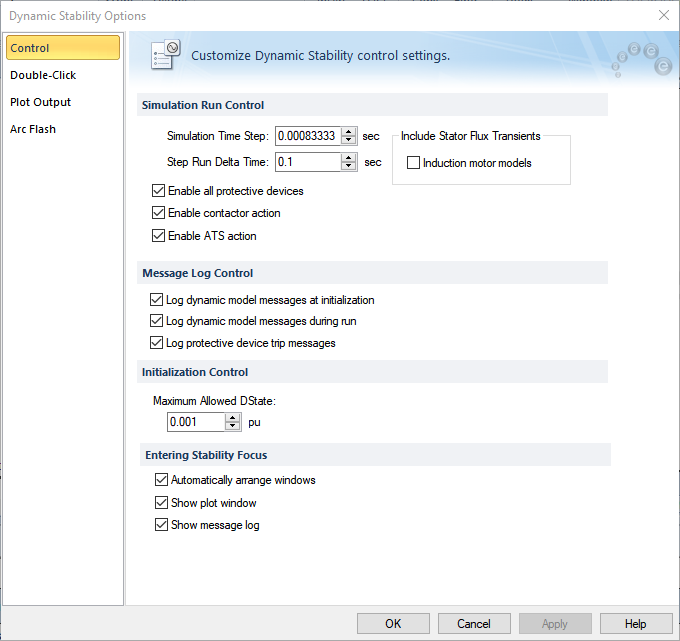
Figure 1: Dynamic Stability Options - Control
| Option | Description |
|---|---|
|
Simulations Run Control |
|
|
Simulation Time Step |
The simulation calculations are performed after every time step (or interval) in seconds. A smaller time step can result in improved accuracy, at the cost of longer simulation completion time. Very large time steps can lead to numerical instability. It is recommended that the time step be smaller than half of the smallest time constant in equipment data. |
|
Step Run Delta Time |
When a simulation is run one step at a time, this is the duration of each run. Step Run is available only with simulation scripts. |
|
Enable all protective devices |
The tripping of protective devices such as relays, circuit breakers, and fuses are enabled during dynamic stability simulations. |
|
Enable contactor action |
Selecting this check box enables contactors to drop out automatically when the voltage drops. |
|
Enable ATS action |
Selecting this check box enables ATS to switch to the alternate source automatically when the primary source is disconnected. |
|
Include Stator Flux Transients |
You can include the effect of transient dc offset in your simulations. Dynamic simulations are normally run in symmetrical rms values. Including the transient dc components in the calculations makes the simulation more realistic. You can include stator flux transient models for the following machine models for induction motors and synchronous motors. |
|
Message Log Control |
|
|
Log dynamic model messages at initialization |
Enabling this option outputs messages in the Message Log regarding the initialization status all equipment with dynamic stability data. |
|
Log dynamic model messages during run |
Enabling this option outputs messages in the Message Log regarding the events that occur during the simulation. |
|
Log protective device trip messages |
When protective devices trip during a simulation, the message log will include the event. |
|
Initialization Control |
|
|
Maximum Allowed DState |
Prior to running a dynamic simulation, the steady state initial condition is determined using this value as the criteria. The DState is the difference between the values of a variable during consecutive steps of computation. When all the DStates settle down to values below the Maximum Allowed DState, the initialization is considered complete. In general, the smaller the value specified for the Maximum Allowed DState, the more accurate is the initialization. However, reducing the value too low can cause failure of initialization or take longer time to settle. |
|
Entering Stability Focus |
|
|
Automatically arrange windows |
When you enter the Dynamic Stability focus, the windows are automatically arranged such that you can view all of the open windows. These windows include the one-line window, and any of the plot and message windows if they are enabled in the Dynamic Stability Options. |
|
Show plot window |
Displays the Dynamic Stability Plot window while entering Dynamic Stability focus. |
|
Show message window |
Displays the Dynamic Stability Message Log window while entering Dynamic Stability focus. |