|
Short Circuit Reports
|
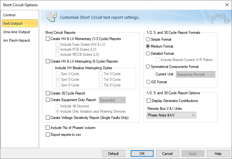
Five different text reports are available during short circuit analysis: Momentary, Interrupting, 30 cycle, Equipment Duty, and Voltage Sensitivity. You can view the results onscreen or print them. EasyPower can display multiple result windows at one time and you can study them using the Window > Tile features.
Note: The ability to automatically check equipment duties during analysis is only available if you have purchased the SmartDuty™ option to EasyPower.
Text output to the result windows are independent of one-line output.
For example, you might want to study detailed text results of momentary and 30 cycle currents while displaying equipment duty results on the one-line. To do this, select the Momentary and 30 cycle check boxes in the Text Output tab of the Short Circuit Options dialog box. Click  Equipment Duty. When a fault operation is done, EasyPower automatically applies the necessary faults for duty analysis and displays the results on the one-line. In addition, the momentary and 30 cycle faults are performed and displayed in the text result windows. Equipment Duty. When a fault operation is done, EasyPower automatically applies the necessary faults for duty analysis and displays the results on the one-line. In addition, the momentary and 30 cycle faults are performed and displayed in the text result windows.
Note: The voltage sensitivity operation only tabulates momentary text results, regardless of what you might have chosen for the one-line's voltage sensitivity display.
|
|
Include Fuse Duties (HV & LV)
|
The fuse interrupting currents are displayed in the High and Low Voltage Momentary result window since fuses open under momentary currents.
Fuse multiplying factors are based on the fault point X/R ratio and the fuse test X/R ratio. The interrupting currents are calculated by adjusting the symmetrical current if the equipment test X/R is less than the fault point X/R ratio. The following equation is used to determine the currents:
Iadjsym =Isym [1 + 2e{-4πÁsys /(X/Rsys)}]1/2 / [1 + 2e{-4πÁsys /(X/RTest)}]1/2
Á= 0.49 - 0.1 e-(X/R)/3}
Standard test X/R ratios are 5, 8, 12, and 15 for distribution and power fuses. See Reference1.
Reference:
1 IEEE Standard Design Tests for High Voltage Fuses, Distribution Enclosed Single Pole Air Switches, Fuse Disconnecting Switches, and Accessories, C37.41-1988.
|
|
Include HV Breaker Interrupting Duties
|
This option lets you display ANSI standard interrupting duty currents for high voltage breakers. The breaker interrupting results are displayed in the High Voltage Interrupting result window according to the interrupting time chosen under the Cycles option (3, 5, & 8 cycles).
The interrupting currents are calculated by adjusting the symmetrical current by a multiplying factor. For breakers, the multiplying factor is based on the fault point X/R ratio, the No AC Decay (NACD) ratio, the contact parting time of the breaker, and whether the breaker is rated on a Total or Symmetrical basis. The NACD ratio consists of two factors dependent upon whether generation is Local or Remote. The equations and calculation procedures are too detailed for this discussion. If additional information is required refer to the References2,3,4 below.
Reference:
2 Sample System for Three Phase Short Circuit Calculations, Conrad St Pierre, IEEE/IAS Mar/Apr 1990.
3 Interpretation of New American National Standards For Power Circuit Breaker Applications, Walter C. Huening Jr., IEEE/IAS Sept/Oct 1969.
4 AC High Voltage Circuit Breakers Rated on a Symmetrical Current Basis, ANSI/IEEE Std. C37.010-1979.
|
|
Include LV Breaker Duties
|
This option displays low voltage power circuit breaker (LVPCB) and molded case circuit breaker (MCCB) interrupting currents for low voltage momentary faults. The results are displayed in the Low Voltage Momentary result window. Notice that under ANSI terminology, when the term interrupting is used for low voltage equipment, it applies to momentary or 1/2 cycle faults. This is because low voltage equipment typically interrupts within 1/2 cycle of fault inception.
The interrupting currents are calculated by adjusting the symmetrical current if the equipment test X/R is less than the fault point X/R ratio (see References 5,6 below). The following equation is used to determine the currents:
Iadjsym = Isym [1 + e{-2πÁ/(X/Rsys)} ] / [1 + e{-2πÁ/(X/RTest)} ]
Á= 0.49 - 0.1 e{-(X/R)/3}
X/Rtest = TAN[ARCCOS(Tested PF)]
|
Low Voltage Power Circuit Breakers
|
15%
|
|
Molded Case Circuit Breakers over 20 kA
|
15-20%
|
|
Molded Case Circuit Breakers between 10-20 kA
|
25-30%
|
|
Molded Case Circuit Breakers between 0-10 kA
|
45-50%
|
|
Low Voltage Fuses
|
20% or 50%
|
Reference:
5 Low Voltage Power Circuit Breakers Used in Enclosures, ANSI/IEEE Std. C37.13-1981.
6 Low Voltage Power Circuit Breakers, NEMA Publications BU-195x, and BU1-1972.
|
|
Create Equipment Duty Report
|
Creates a report with current flows through every breaker and evaluates the fault currents (breaker duty) in percentage of the breaker rating. You can specify whether to include all devices or only those devices that have violations or warnings.
|
|
Create Voltage Sensitivity Reports
|
Creates reports listing all buses which have voltages below a specified threshold when a fault occurs in the system.
|
|
Include 'No. of Phases' Column
|
This check box controls whether the number of phases is displayed in a column on the text reports. By default, this option is not selected.
|
|
Export reports to CSV
|
When this check box is selected, the output from the short circuit and equipment duty reports are saved as CSV (comma separated value) files. The files are stored in the same directory as the .DEZ file. Each time you run a new report, the previous file is overwritten unless you change the name of the original file.
|
| 1/2, 5 and 30 Cycle Report Formats |
Three types of text output styles are available, ANSI, Symmetrical Components, and GE. The ANSI style is designed for reporting all the significant ANSI Standard breaker comparison multipliers and results for standard protective relaying requirements. If you select the ANSI output style, three different output formats are available. Levels 1-3 provide the standard format designed for equipment duty comparison and relaying currents. Level 3 contains the most detailed information.
The symmetrical component style is designed specifically for specialized relaying purposes that require a component output for both voltages and current. You are encouraged to try different options and levels of details for your particular study requirements.
The other option is GE, which is the popular General Electric short circuit format.
|
|
Include Branch Current X/R Ratios
|
Lets you display branch X/R ratios for each contributing branch current.
|
| Display Generator Contributions |
Displays generator and utility voltages and currents for each fault.
|
|
Remote Bus V&I Units
|
These options let you display remote bus results in Sequence Per-unit, Phase Amps & kV, or Phase Per-unit format.
|
|
Default
|
In the Short Circuit Options Defaults dialog box, you can specify which default short circuit option settings you want to use. This affects the settings in the entire dialog box and is not limited to only the currently selected tab. These default settings are used for all new one-lines.
The options are:
-
Store Current Options as Default Settings: This stores all of the current short circuit options in your equipment defaults file.
-
Reset Current Options to Default Settings: This updates all of the current short circuit options based on those you stored previously in your equipment defaults file.
-
Reset Current Options to Factory Settings: This updates all of the short circuit options to match the defaults that are included in the initial installation of the EasyPower program.
Default settings specified here only affect ANSI settings.
|