TCC Options
TCC options can be used in the Coordination focus to select the type of fault, the short circuit values, the calculation type, and the output pictures in the TCC plots. When the TCC window is open, click  TCC Options from the TCC tab.
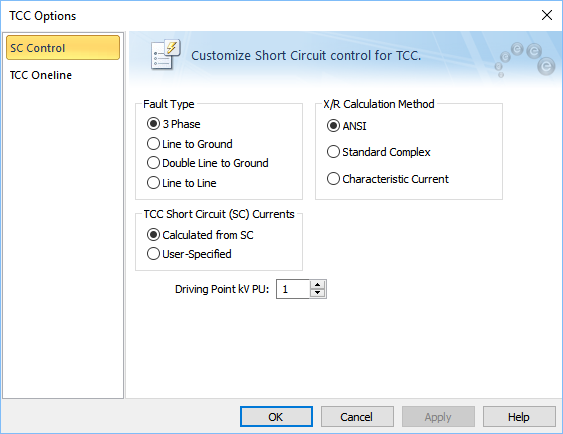
Figure 1: SC Control Tab of TCC Options Dialog Box
Note: If the system options are set to IEC-60909, the X/R Calculation Method area is not displayed.
Short Circuit Control Tab
Option Descriptions
|
Option
|
Description
|
|
Fault Type
|
Four different types of faults are available during a short circuit analysis. The default is 3 Phase, which is generally used to determine the highest available currents for equipment duty comparisons, and relaying. You can also select 3 Phase fault by clicking  3-Phase on the TCC tab. 3-Phase on the TCC tab.
The other types, Line to Ground, Double Line to Ground, and Line to Line are generally used for specialized relaying applications or system trouble shooting. The green dots in the buttons indicate the ground fault type.
|
|
TCC Short Circuit Currents
|
The short circuit currents used in the TCC can be calculated from short circuit or user-specified.
- Calculated from SC: EasyPower calculates the maximum fault current that may pass through the protective device. The selection for TCC short circuit (SC) currents can also be made in the Coordination Options dialog box.
- User-Specified: You must enter the short circuit current in the Short Circuit tab of the device data dialog box or the temporary data dialog box of the protective device to use TCC clipping or to show the tick mark on the TCC plot.
|
|
[IEC DC] Driving Point kV PU
|
System fault point voltage in per-unit. This value defaults to 1.0 per-unit.
|
|
X/R Calculation Type
|
Note: Not applicable to IEC.
Short circuit calculations are based on one of three methods:
After each dc component is determined and totaled, the equivalent X/R ratio is found from the equation below.
Equivalent X/R = -p/ ln (S IDC / S IAC RMS SYM / Ö2)
The CCM method provides a conservative approach to obtain the fault point X/R ratio and appears to do the best overall job without being over-conservative.
|
Reference:
1 Parise G., A new approach to calculate the decaying AC contributions to short-circuit: the ‘characteristic’ currents method; IEEE Transactions on Industry Applications, Vol. 31, No. 1, January/February 1995.
TCC One-line Tab
The contents of the One-line Output tab of the TCC Options dialog box are the same as those described for Short Circuit Options dialog box. See One-line Output Tab or One-Line Output Tab (IEC) for more information.
Next: Arc Flash Hazard Analysis in Coordination Focus
More Information