One-Line Output Tab (IEC)
To set short circuit options, from the Short Circuit focus, click SC Options. You can also access the options from within the Database Edit focus by selecting Tools > Options > Analysis Options > Short Circuit.
Select the One-line Output tab to specify various parameters for controlling what is output to the one-line during the short circuit study.
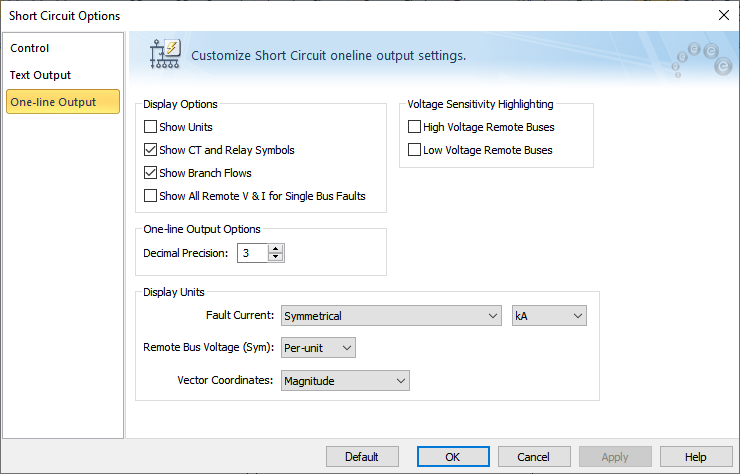
Figure 1: One-line Output Tab of the Short Circuit Options Dialog Box
Option Descriptions
| Option |
Description |
|
Display Options
These options enable you to control what appears on the one-line while performing short circuit calculations.
|
| Show Units |
Select for short circuit results to appear with their corresponding units, such as kA, MVA, or pu for branch flows and kV(LL) or pu for voltages. |
| Show CT and Relay Symbols |
Select for the symbols for current transformers and relays to appear in the one-line. |
| Show Branch Flows |
Select to display branch flows during a short circuit. If these are not selected, only the bus fault current appears on the one-line. |
|
Show All Remote V&I for Single Bus Faults
|
Select for the branch flows and bus voltages to appear on all branches and buses. With this option, you do not need to perform a separate Remote Bus V&I command.
|
| One-Line Output Options |
| Decimal Precision |
This sets the number of digits past the decimal point for values displayed on the one-line. |
| Display Units |
| Fault Current: |
Fault Current: Enables you to choose the unit of fault current and the type of current. You can display on the one-line the following types of currents:
- Symmetrical: rms value of AC component.
- Asymmetrical: rms value of AC and DC components combined (total).
- Max Sym and (Max Asym): The maximum phase current among the three phases. Both AC symmetrical rms and asymmetrical rms values are displayed, with the asymmetrical values appearing in parentheses.
- Max Sym and (Max Momentary Peak): The maximum phase current among the three phases. Both initial AC symmetrical rms (Ik”) and peak (Ip) values are displayed, with the peak values appearing in parentheses.
The following fault current units are available for display in the one-line:
|
|
Remote Bus Voltage (Sym)
|
Voltages can be displayed as symmetrical voltage in either physical units (kV) or in per-unit values.
|
| Voltage Sensitivity Highlighting |
| High and Low Voltage Remote Buses |
This option highlights all buses on the one-line with voltages below a user-specified threshold value for a single fault. Voltage sensitivity studies are used to determine problem areas which may cause contactor dropout or equipment failure for critical areas such as boiler feed water pumps, ID fans or drive systems. Refer to the Control tab of the Short Circuit Options dialog box for setting the threshold value.
Both high and low voltage remote buses can be studied.
|
| Vector Coordinates |
Enables display format as:
- Magnitude
- Magnitude and Angle
- Real and Imaginary
|
|
Default
|
In the Short Circuit Options Defaults dialog box, you can specify which default short circuit option settings you want to use. This affects the settings in the entire dialog box and is not limited to only the currently selected tab. These default settings are used for all new one-lines.
The options are:
-
Store Current Options as Default Settings: This stores all of the current short circuit options in your equipment defaults file.
-
Reset Current Options to Default Settings: This updates all of the current short circuit options based on those you stored previously in your equipment defaults file.
-
Reset Current Options to Factory Settings: This updates all of the short circuit options to match the defaults that are included in the initial installation of the EasyPower program.
Default settings specified here only affect IEC settings.
|
More Information