EasyPower 10.6 Release Details
This topic describes new EasyPower features and enhancements, as well as bug fixes that are included in the release.
Note: New release features often include changes to the database. This may affect what you see in the Database Browser and also what is included when you export data into CSV files. If your existing work processes rely on information from the database, be sure to review your processes after you update your software.
Features and Enhancements
Click this link to watch a video of all the new features.
Data Collection with Camera Integration
Click this link to watch a video of this feature.
Within EasyPower, new features now allow you to take pictures with your computer's built-in camera or an external camera and immediately associate pictures with specific equipment in your model. You can also add names, notes, and tags to pictures within EasyPower.In the individual equipment data dialog boxes, there is a new option to capture an image.
![]()
When you select this icon, you are given a choice of taking a photo with the device's camera or to wait for a photo to be taken with an external camera.
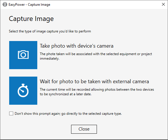
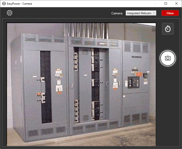
If you select Take a photo with the device's camera, a camera dialog box opens where you can specify camera settings, select a camera, and take a photo.
If you select Wait for photo to be taken with external camera, you can specify the capture start and end times and provide additional file details.
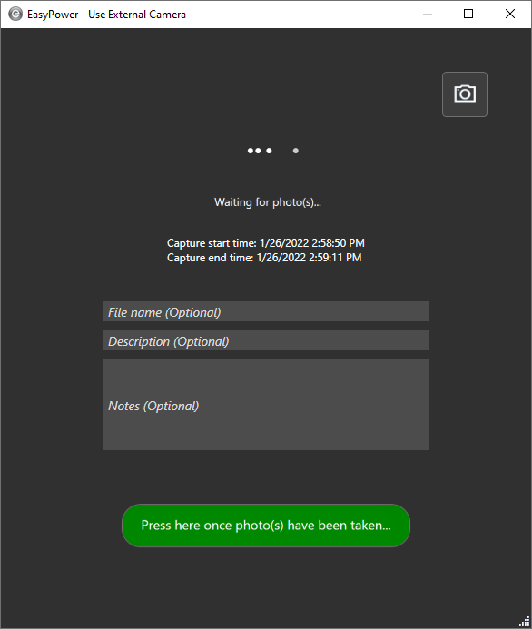
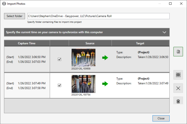
Photos taken with an external camera can be synchronized with the capture times for importing at a later time. When synchronizing images, the following formats are supported: .JPG, .JPEG, .PNG, .TIF.
![]()
Similar functionality is available from within Media Gallery:
![]()
Note that the original Add, Delete, and Link buttons have been replaced with new icons in the Media Gallery and equipment data dialog boxes.
![]()
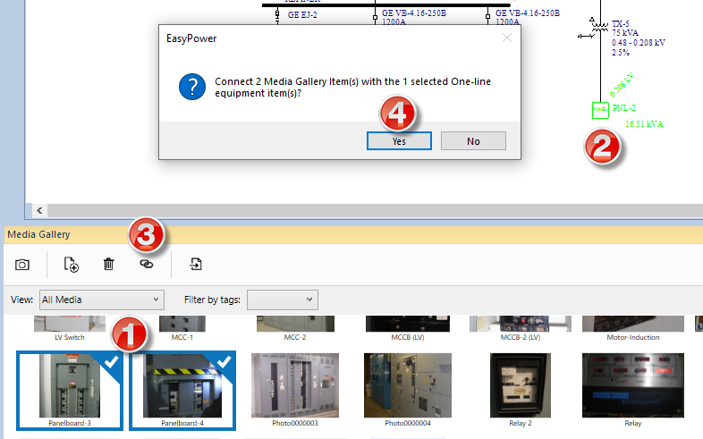
You can now link one or more Media Gallery items to one or more selected items on your one-line without having to open the individual equipment data dialog boxes.
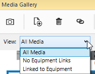
You can now filter the Media Gallery to view:
- All Media
- Media with No Equipment Links
- Media that is Linked to Equipment
For more information, refer to the topics in Media Gallery.
Boundary Calculations for User-Specified Arc Flash PPE Ratings
Click this link to watch a video of this feature.
Advanced Arc Flash Options
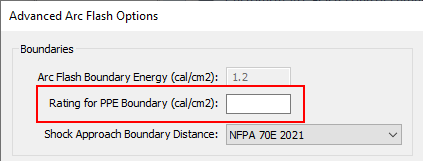
A new option is available to calculate an additional boundary for arc flash--the PPE Boundary. The PPE Boundary is the distance at which the available incident energy is equivalent to the user-specified PPE Rating. You can set the Rating for PPE Boundary in the Advanced Arc Flash Options. Use this option to set a specific energy value for which you would like a distance calculated in addition to the normal arc flash boundary calculation. This option applies only when the arc flash hazard standard is set to use IEEE 1584-2018.
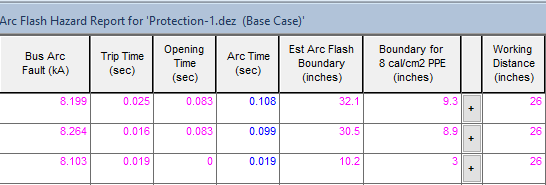
For example, you might want to calculate the distance from the fault where the incident energy would be 8 cal/cm2. You can do this by setting the Rating for PPE Boundary value to 8. Now, when running arc flash you can view a column with the text “Boundary for 8 cal/cm2 PPE (inches).” This value represents the distance from the arc flash event where the incident energy is 8 cal/cm2. This column is not part of the default Arc Flash Hazard Report configuration but you can add it using Report Configuration.
The value can be calculated in cal/cm2 or Joules/cm2 depending on the Display Incident Energy in option specified in the Short Circuit Options > Arc Flash Hazard settings.
Arc Flash Labels
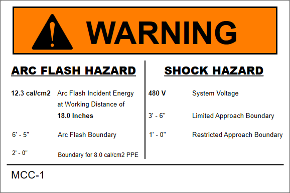
There are new variables available for arc flash labels to display the PPE Boundary, PPE Boundary Value, and Rating for PPE Boundary value.
The example below shows an arc flash label with the PPE Boundary and Rating for PPE Boundary (cal/cm2) included.
Scenario Comparison Reports
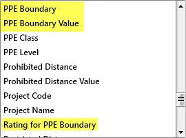
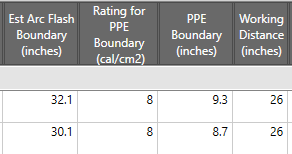
Although the Rating for PPE Boundary and PPE Boundary are not part of the Default view, you can add it to a custom view.
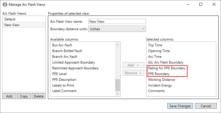
The columns appear towards the end of the report.
Work Permits
There are two new variables that you can add to your work permits:
- PPE Boundary: {PB}
- PPE Boundary Energy: {PN}
These are not part of the default work permit template, but you can add them to a custom template. See Editing Work Permits for more information.
TCC Title Block - Linked or Custom Names
Click this link to watch a video of this feature.
You can now link the name on the TCC title block to the name of the stored TCC. If you store the TCC with a different name, the name on the TCC title block is automatically updated.
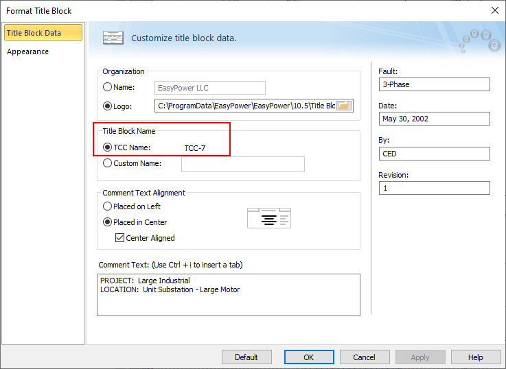
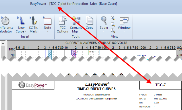
Note that you can continue to use custom names on your TCC title block, if desired. When you use this option, the name in the TCC title block can be different from the stored TCC name.

When a database file that contains existing TCCs is upgraded from a previous version:
- If the TCC title block name does not match the stored TCC name, the Custom Name option is selected and the existing TCC title block name is assigned as the custom name.
- If the TCC title block and stored TCC names match, the TCC Name option is used.
Retain Defaults When Upgrading
When you upgrade EasyPower from a prior version (10.0 or later), your custom equipment default settings are automatically retained. The equipment defaults file (Default.db) contains your equipment default settings and if upgrading from version 10.5, it also includes your Short Circuit Option default settings.
Examples
The examples below show an upgrade from 10.5 to 10.6, but the behavior would be the same for any prior 10.x version being upgraded to version 10.6.
In all the examples below, the resulting equipment defaults file (Default.db) is created and stored in C:\Users\{Name}\Documents\EasyPower 10.6\Equipment Defaults\.
Starting EasyPower 10.6 for the first time with no prior version of EasyPower installed:
- The Default.db file is created when a one-line is opened or created.
- The program uses the factory defaults.
Starting EasyPower 10.6 for the first time after upgrading from EasyPower 10.5:
- The equipment defaults file is copied from C:\Users\{Name}\Documents\EasyPower 10.5\Equipment Defaults\Default.db and the file is upgraded to 10.6 the first time it is opened.
- The program uses the same equipment defaults that were set up in EasyPower 10.5.
Starting EasyPower 10.6 for the first time after upgrading from EasyPower 10.5, where the equipment defaults are stored in a custom network location:
This example assumes a custom network location named K:\Corporate Standards\MyCustomDefaults.db having been specified in the EasyPower 10.5 File Locations settings.
- The equipment defaults file is copied from K:\Corporate Standards\MyCustomDefaults.db and the file is upgraded to 10.6 the first time it is opened.
- The program uses the same equipment defaults that were set up in EasyPower 10.5.
Note: If no equipment defaults file is found in the custom location specified, the program creates the equipment defaults file as if it were a new installation and uses the factory defaults.
If you want to use the same defaults file in a networked location so that future adjustments to your custom defaults are shared with others, you still need to manage that manually by changing the path in File Locations. See File Locations Tab for more information.
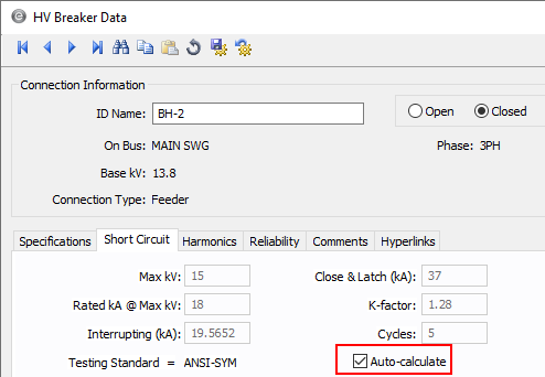
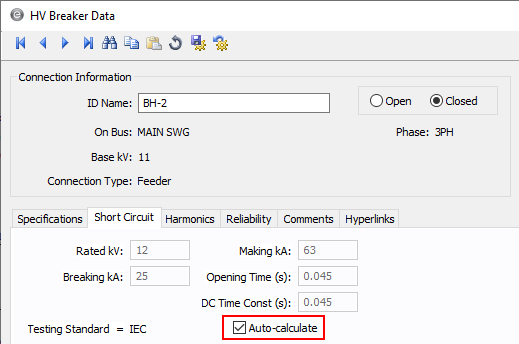
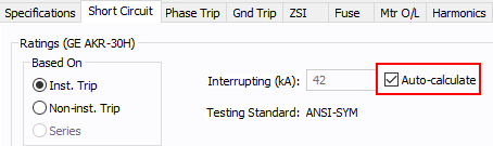
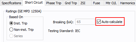
Auto-Calculate Added for HV Breakers
Click this link to watch a video of this feature.
Short circuit information is now automatically calculated based on the manufacturer library information. You can also choose to disable auto-calculation and enter this data manually.
The Calculate button has been removed from the data dialog box and replaced with an Auto-calculate checkbox.
Note: For .DEZ files created in EasyPower 10.5 and earlier, this checkbox is not selected. This prevents your values from being overwritten when you open the data dialog box for the first time after upgrading. The checkbox is automatically selected for newly added breakers unless you change the default settings in your equipment defaults.
ANSI:
IEC:
Auto-Calculate Added for LV Breakers
Click this link to watch a video of this feature.
Short circuit information is now automatically calculated based on the manufacturer library information. You can also choose to disable auto-calculation and enter this data manually.
The Calculate button has been removed from the data dialog box and replaced with an Auto-calculate checkbox.
Note: For .DEZ files created in EasyPower 10.5 and earlier, this checkbox is not selected. This prevents your values from being overwritten when you open the data dialog box for the first time after upgrading. The checkbox is automatically selected for newly added breakers unless you change the default settings in your equipment defaults.
ANSI:
IEC:
Bug Fixes
The following issues have been addressed in this release:
Arc Flash
- Fixed an issue in the integrated method of arc flash where the trip time in inverters and AFDs was not being used.
Coordination
- Fixed an issue where some additional curves would appear for devices in the TCC after enabling the Synch TCC one-line colors to TCC curve colors option in TCC Options.
- Fixed a graphics issue in the TCC one-line with disconnected protective devices where the ATS is flipped.
- Fixed an issue with TCCs for relays with the Time Adder and Minimum Time settings where the inverse curve is faster than the instantaneous time delay. This is an atypical setting for relays.
- Fixed an issue where some curves were missing in print preview or print to PDF during batch printing.
- For certain solid state trip breakers that offer a choice between Instantaneous Override and Max Instantaneous Setting, the text for these were switched in the LV Breaker Data dialog box in EasyPower versions 10.0 through 10.5. See List of Affected Solid State Trip (SST) Devices with Switch Between Instantaneous Override and Max Instantaneous Setting for a list of devices you may need to review to ensure the appropriate settings are used.
- Fixed an issue where selected items on a TCC one-line could not be moved.
- Fixed an issue where using Undo after moving a curve on the TCC plot was not resetting the curve back to its original settings.
- Fixed an issue where EasyPower displayed a warning message and terminated unexpectedly when attempting to print multiple TCCs that contain an ATS to a single file.
- Fixed an issue where some curves were missing in print preview or print to PDF while batch printing.
- Fixed an issue in TCC plots where pickup tick marks overlapped for the device functions of the same relay.
Drawings
- Fixed an issue where the colors specified for warning and analysis buses were not displayed during print preview or print to PDF.
One-Line Display
- Fixed an issue where a relay's data text overlapped the relay symbol.
Power Flow
- Fixed an issue where total losses were displayed incorrectly on reports.
Revit Integration
The Revit parameter Short Circuit Rating for equipment is now considered to be in kA unit as the default. This allows for improved mapping between Revit and EasyPower. Please review your mapping configuration file and update if necessary.
Scenarios
- Fixed an issue where the location description for an ATS was missing on the Arc Flash Scenario Comparison report.
- Fixed an issue where the Equipment Duty Comparison report did not properly show the worst-case result when different types of equipment shared the same name.
Short Circuit
- Fixed an issue where equipment duty does not include symmetrical duty for high voltage switches.
- Fixed an issue with IEC short circuit where fault currents were not showing in the presence of motors with a DC drive.
- Fixed an issue where line end fault results were not displayed on the one-line.
List of Affected Solid State Trip (SST) Devices with Switch Between Instantaneous Override and Max Instantaneous Setting
Manufacturer | Type | Style |
|---|---|---|
| Eaton | IZM | XZMU |
| GE | M-Pact | M-PRO 17 |
| GE | M-Pact | M-PRO 20 |
| GE | M-Pact | M-PRO 30 |
| GE | M-Pact | M-PRO 40 |
| Moeller | IZM | XZMU |
| OEZ | ETU 45B [IEC] | Arion WL12 |
| OEZ | ETU 45B [IEC] | Arion WL13 |
| OEZ | ETU 55B [IEC] | Arion WL11 |
| OEZ | ETU 55B [IEC] | Arion WL12 |
| OEZ | ETU 55B [IEC] | Arion WL13 |
| OEZ | ETU 76B [IEC] | Arion WL11 |
| OEZ | ETU 76B [IEC] | Arion WL12 |
| OEZ | ETU 76B [IEC] | Arion WL13 |
| Siemens | ETU 45B | WL FS II |
| Siemens | ETU 45B | WL FS III |
| Siemens | ETU 45B [IEC] | 3WL5 |
| Siemens | ETU 45B [IEC] | WL FS I [IEC] |
| Siemens | ETU 745 L(SIG) | ICCB WL FS I |
| Siemens | ETU 745 L(SIG) | ICCB WL FS II-C |
| Siemens | ETU 745 L(SIG) | ICCB WL FS II-L |
| Siemens | ETU 745 L(SIG) | ICCB WL FS II-S |
| Siemens | ETU 745 L(SIG) | ICCBWL FS III-C |
| Siemens | ETU 745 L(SIG) | ICCBWL FS III-L |
| Siemens | ETU 745 L(SIG) | WL FS I |
| Siemens | ETU 745 L(SIG) | WL FS II |
| Siemens | ETU 745 L(SIG) | WL FS III |
| Siemens | ETU45B [IEC] | 3WL11 |
| Siemens | ETU45B [IEC] | 3WL12 |
| Siemens | ETU45B [IEC] | 3WL13 |
| Siemens | ETU76B [IEC] | 3WL11 |
| Siemens | Sensitrip III | JD |
| Siemens | Sensitrip III | JD Frame |
| Siemens | Sensitrip III | LD |
| Siemens | Sensitrip III | LD Frame |
| Siemens | Sensitrip III | LD Frame LI |
| Siemens | Sensitrip III | MD |
| Siemens | Sensitrip III | MD Frame |
| Siemens | Sensitrip III | MD-InstxIn |
| Siemens | Sensitrip III | ND |
| Siemens | Sensitrip III | ND Frame |
| Siemens | Sensitrip III | ND Frame LIG |
| Siemens | Sensitrip III | PD |
| Siemens | Sensitrip III | PD Frame |
| Siemens | Sensitrip III | PD Frame (LIG) |