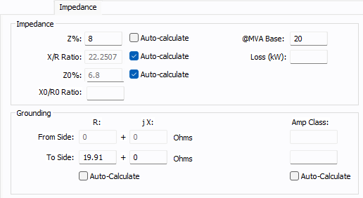
Figure 1: Impedance Tab (3-phase)
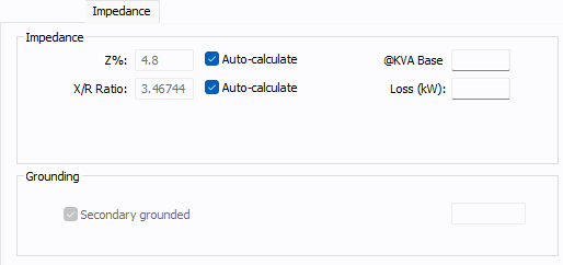
Figure 2: Impedance Tab (Single-phase)
| Option | Description |
|---|---|
|
Transformer nameplate impedance in percent. By definition, this is the positive sequence leakage impedance in percent on the self-cooled MVA and nominal voltage rating. The strict definition is the percent of rated voltage impressed on the high voltage winding to produce rated full load current in the short circuited low voltage winding. You can enter a value if the Auto-calculate checkbox is clear, or select the checkbox to have the program calculate the value. For the Z% auto-calculate functions, the following sources are used:
If Loss (kW) is not entered, the calculated X/R ratio curve is based on the medium ANSI Standard curve [ANSI C37.010-1979]. This curve was developed mainly for power transformers and is typically high for low voltage unit substations less than 2500 kVA. If the Standard selected on the Specifications tab is set to IEC, the impedance is based on the MVA O/L value instead of the MVA rating. Center-Tap Transformer Impedances: For center-tapped transformers with 1PH-3W secondaries, the resistance and reactance are multiplied by 1.5 and 1.2 respectively if a line-to-neutral fault is applied. Reference: Beeman, D., Industrial Power System Handbook, McGraw-Hill Book Company in NY, 1955, page 75. |
|
|
@MVA Base @kVA Base |
The base rating at which the Z% and Z0% impedances are applicable. The kVA or MVA text is displayed depending on the rating unit selected in the Specifications tab. When the field is blank, the program uses the standard ratings indicated on the Specifications tab to calculate the transformer per unit impedances:
You can also enter the MVA or kVA base values from the transformer datasheet or nameplate. When you manually enter a value, the entered value is used to calculate the per unit impedances instead of the standard ratings. |
|
Loss (kW) |
This is the kW losses at full load. Auto-calculate uses this value to obtain the X/R ratio for the positive sequence impedance (Z%). The equation used is:
This field can be left blank. When this field is blank, the X/R ratio is estimated using the ANSI C37 curves. |
|
X/R Ratio |
Transformer reactance to resistance ratio, which is used to determine resistance value. You can enter a value if the Auto-calculate checkbox is clear, or select the checkbox to have the program calculate the value. |
|
Z0% |
Transformer zero sequence leakage impedance in percent. If you don't know this value, enter the positive sequence impedance (Z) for shell transformers (see Form field above). For core transformers, use approximately 85% of Z. If you enter this value as zero (0.0), the positive sequence impedance is used. If Z% is entered, you can use Auto-calculate to compute the Z0% value if it is blank. |
|
X0/R0 Ratio |
X/R ratio for zero sequence impedance (Z0%). Enter this data from the manufacturer, if available. If this field is left blank, zero sequence R0+jX0 values are calculated based on the positive sequence X/R ratio. |
|
Grounding Grounding impedances only apply to wye grounded connections. The units are R+jX in ohms. |
|
|
R |
Transformer neutral ground resistance in ohms. This is the most common method of grounding the transformer neutral winding. Grounding resistors are usually given in amperes. The impedance is found from the following equation. R = Vln / I If the transformer is grounded through a separate grounding transformer with a secondary resistance, this resistance must be converted to the primary winding. Only wye grounded transformers are modeled with grounds. Mid or corner tapped delta windings are not modeled. You can enter a value if the Auto-calculate checkbox is clear, or select the checkbox to have the program calculate the value. |
|
jX |
Transformer neutral ground reactance in ohms. You can enter a value if the Auto-calculate checkbox is clear, or select the checkbox to have the program calculate the value. |
|
Amp Class |
This is the current in amps through the ground impedance at the rated voltage. You can enter a value if the Auto-calculate checkbox is clear, or select the checkbox to have the program calculate the value. |
|
Secondary Grounded |
All 1PH transformers are modeled as grounded on the secondary side. |
|
IEC |
|
|
pT % |
For generator step-up (GSU) transformers, you can specify an impedance correction factor. The range is from -20% to 20%. This appears only if the option is set to Show fields and X/R calculations based on IEC 60909 in Tools > Options > Equipment. |

More Information
- Two Winding Transformer Data
- Database Dialog Box Toolbar
- Two Winding Transformer - Connection Information
- Two Winding Transformer - Specifications Tab
- Two Winding Transformer - TCC Tab
- Two Winding Transformer - LTC (Load Tap Changer) Tab
- Two Winding Transformer - Harmonics Tab
- Two Winding Transformer - Stability Tab
- Two Winding Transformer - Reliability Tab
- Two Winding Transformer - Location Tab
- Two Winding Transformer - Comments Tab
- Two Winding Transformer - Hyperlinks Tab
- Two Winding Transformer - Collected Data Tab
- Two Winding Transformer - Media Gallery Tab