Adding Items to the One-line
Editing such as selection and dragging are done with the  Select pointer. When you click one of the items of the Equipment Palette or Insert tab, the pointer appearance changes to match that item. For example, when you click
  Motor, the pointer changes to a
  Motor symbol. When you click the left mouse button on the one-line, EasyPower puts a motor on the one-line. Depending on your settings, the pointer remains as a motor symbol or changes back to a selection pointer. To change from an equipment icon to the selection pointer manually, click Select in the Equipment Palette or press ESC on the keyboard.
Any time a new item is created, it is given a unique ID name composed of the item type followed by a number. For example, if you add a Bus, the ID name might be "BUS-12." You can change the ID name at any time as described in Changing ID Names.
Buses
The central equipment type of every one-line is the bus. A bus defines the connection point for two or more pieces of equipment. Equipment items which are not yet connected to a bus are highlighted in red.
To add a bus to the one-line, click  Bus in the Equipment Palette or Insert tab. The pointer changes to the shape of a bus as you move back to the one-line. Click on the location where you want to position the bus. You can continue adding buses in this way until you click on another palette button.
You can lengthen or shorten a bus by dragging one end with the left mouse button. There is a default size when you place a bus on the one-line, but you can also shrink the bus down to a single dot or “node.”
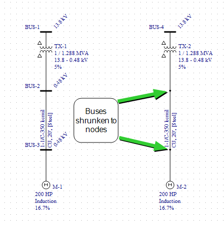
Figure 1: Shrinking Buses to Nodes
Setting Bus kV
When you add a bus to the one-line, you must provide the kV of that bus before you can attach anything to it. You can either set a default kV ahead of time (before adding the bus to the one-line) by clicking Tools > Equipment > Bus and specifying the base kV, or you can set it afterward by double-clicking on the bus to bring up its data dialog box.
EasyPower also allows you to set the kV of more than one bus at a time by using Copy and Paste as described in Copying an Item's Database Information.
Changing Bus Area and Zone
Area numbers are used to uniquely define different areas of the electrical system. These areas can then be used for creating specific text reports from analysis operations that represent subsets of the system. For example, typical paper plant areas may be the power house (Area 1), caustic plant (Area 2), pulp mill (Area 3), and paper machine (Area 4). Area numbers are positive integers between 1 and 999.
A zone number is simply a sub-area. This enables even more specific reporting. You may want to define the pulp mill as Area 3 and the digester electrical equipment as Zone 2. Specific reports can then be generated for this combination without including the entire pulp mill or the other digesters.
To change the area or zone of a bus, double-click on the bus to bring up its data dialog box, and then change the number there. Alternatively, you can select many buses and then from the Home tab, click Change > Bus Area-Zone. This brings up a dialog box that lets you specify an area and zone to be assigned to each of the selected buses.
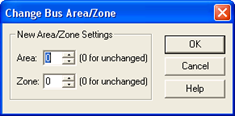
Figure 2: Change Bus Area/Zone Dialog Box
- Area: New area number to assign to the selected buses. Use zero to leave the area unchanged.
- Zone: New zone number to assign to the selected buses. Use zero to leave the zone unchanged.
Equipment with One Connection
Motors, loads, generators, utilities, capacitors, and shunts are placed on the one-line by clicking the appropriate palette button and left-clicking when the pointer symbol's leader is on top of the desired bus. The symbol snaps to the bus. If there is not a bus under the symbol's leader line, the item is highlighted red indicating it is unconnected. You can connect it afterward by dragging the symbol as described in the Equipment with Two or Three Connections.
If you try to connect a piece of equipment to a bus where the base kV has not been specified, the program displays a Set Bus Base kV message. The new equipment is connected after you specify the base kV and click OK. If you click Cancel, the equipment is not attached.
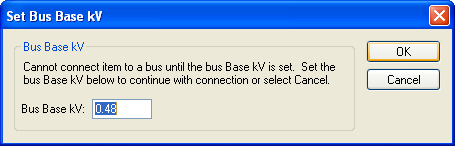
Figure 3: Set Bus Base kV Message
Equipment with Two or Three Connections
Transformers and current limiting reactors are placed on the one-line by choosing the appropriate palette button and left-clicking when the pointer symbol's leader is on top of the desired bus. The symbol snaps to the bus with the remaining leaders turning red to indicate a disconnected state. If there is no bus under any of the symbol's leader lines, the entire item is red as it is completely unconnected.
Use the Select pointer to drag each item to its secondary bus for connection. Drag the symbol so that the unconnected leader is on top of a bus, release the mouse button, and the symbol attaches to the bus.
![]()
Figure 4: Adding a Two-Winding Transformer
Lines Between Buses
When cables, transmission lines, and busways are chosen from the palette, the pointer becomes a crosshair. Put the crosshair on the desired bus and click and hold the left mouse button. This sets one end of the line. Now drag the crosshair to the other bus and release the mouse button to set the other end of the line.
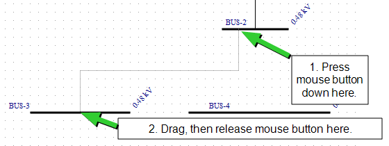
Figure 5: Adding a Cable
Long cables, transmission lines, and busways can be shown as short lines hanging from a bus with the opposite bus labeled on the one-line. This is useful when a line stretches across the one-line and it would take extra work to make room for it. Condensed lines are created by clearing the Show Entire Line check box in the line data dialog boxes. You can resize a condensed line on the one-line.
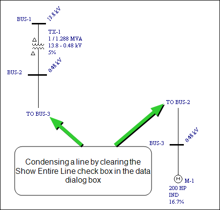
Figure 6: Condensed Line
Feeder Breakers and Switches
A feeder breaker goes between a bus and a piece of equipment. When you choose a voltage breaker or switch from the palette, the mouse pointer changes into the symbol for the selected item, just like it does when you add other types of equipment. To insert a breaker or switch into a line (such as the line between a transformer and its bus), click the mouse while the pointer is on top of that line near a bus. If you miss, the breaker is red, and you will not be able to drag it to the line. It snaps to the bus as a tie breaker, so you must delete it and try again.
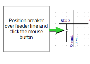
Figure 7: Adding a Feeder Breaker
You can display breaker names and data on the one-line. Click Tools > Options Dialog > Text Visibility.
Figure 8: Breaker Data Checked in Text Visibility
Bus Tie Breakers and Switches
A bus tie breaker or switch goes between two buses rather than between a bus and a piece of equipment.
Click the  LV Breaker palette button.
Place the breaker by positioning the breaker pointer's top leader line on the right end of the bottom middle bus and clicking (see figure below). The breaker automatically attaches to the bus. If you miss (the breaker doesn't connect and stays all red), use the  Select pointer and drag the symbol into position.
Move the pointer over the breaker and right-click. Edit options appear as shown in the figure above. Click Rotate > 90°. The breaker orientation changes from vertical to horizontal. At the same time, the connection type of the breaker changes from feeder breaker to bus tie breaker. Drag the tie breaker's remaining leader to the bottom right bus. After it connects, drag the tie breaker's symbol to be centered between the two buses. After the tie breaker is connected to buses on both sides, the Rotate command only changes the orientation in the one-line diagram, and the bus remains as a tie breaker.
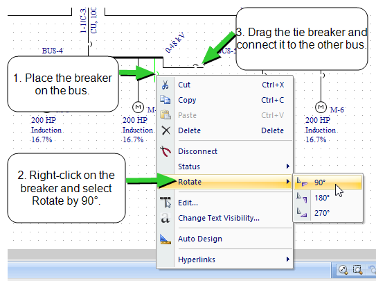
Figure 9: Adding a Tie Breaker
Only one tie breaker per bus is allowed. However, you can model ring buses or breaker and a half schemes by using a breaker inserted into a short section of busway instead of a tie breaker.
Connecting an MCC to an MCC
There may be instances when you would want to connect a motor control center (MCC) to another MCC, a panel schedule to a panel schedule, or a panel schedule to an MCC. MCC and panel items are modeled as buses. You can connect them with cables, busways or transformers.
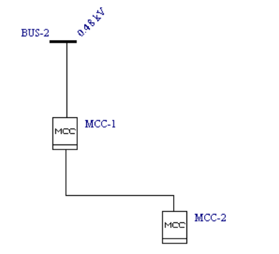
Figure 10: Connecting an MCC to Another MCC
MCC-2 can be specified as a subordinate MCC that feeds off MCC-1, as follows:
- In the Description tab of the upstream MCC dialog, set the Load Type as Sub-MCC.
- In the Sub-Line column, select the cable or transformer that feeds the sub-MCC.
- In the Sub-MCC column, select the ID Name of the subordinate MCC.
- Click Data to specify the protective device and settings.
Auto-insertion of Buses
You can directly add one piece of equipment to another without inserting a bus first. EasyPower creates a bus between the two pieces of equipment you are connecting, as shown below.
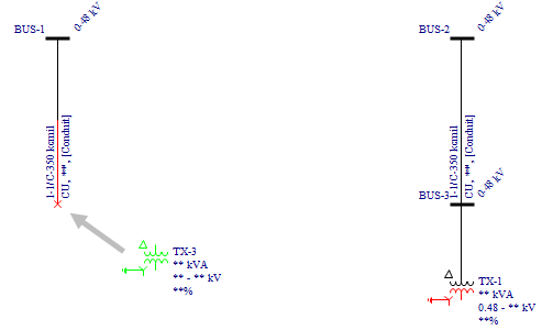
Figure 11: Auto-insertion of Buses
Notes
Notes are used to annotate your one-line with additional text information. For details on how to enter and edit notes, see Notes (Free Text) on One-line.
More Information
| Making One-line Diagrams | Setting Default Equipment Values |
| Changing ID Names | Grouping One-line Items |
| Selecting Items | The Snap Grid |
| Changing the One-line Diagram |
|
|