Control Tab (IEC)
To set short circuit options, from the Short Circuit focus, click SC Options.
Select the Control tab to specify various parameters for controlling the behavior of a short circuit study.
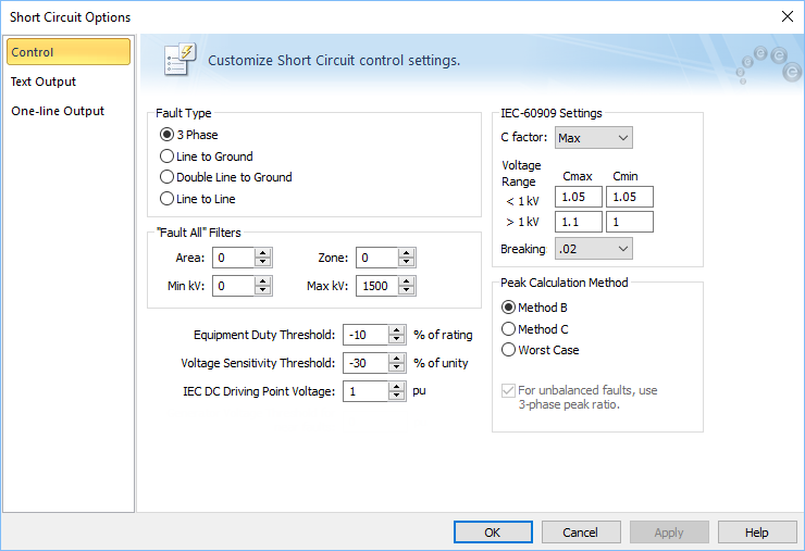
Figure 1: Control Tab of Short Circuit Options Dialog Box
| Option | Description | ||||||||||||
|---|---|---|---|---|---|---|---|---|---|---|---|---|---|
| Fault Type | Four different types of faults are available during a short circuit analysis. The default is 3 Phase which is generally used to determine the highest available currents for equipment duty comparisons, and relaying. The other types, Line to Ground, Double Line to Ground, and Line to Line are generally used for specialized relaying applications or system troubleshooting. | ||||||||||||
| "Fault All" Filters | Enables you to specify a specific bus Area, Zone, and kV Range that to fault and report when you fault multiple or all buses. | ||||||||||||
| Equipment Duty Threshold |
Sets the lower limit for flagging breaker violations in SmartDuty™. If the threshold is set to -10 percent, SmartDuty™ flags all equipment which has short circuit duties within 10 percent of their maximum rating (greater than 90% of their rating). Note: The ability to automatically check equipment duties during analysis is only available if you have purchased the SmartDuty™ option to EasyPower. Note: You must click For more information on IEC equipment duty calculations, see IEC Equipment Duty Calculations. |
||||||||||||
|
You can set a threshold for remote bus voltages. Buses that violate this threshold are highlighted. You can control the highlighting for high voltage and low voltage buses using Short Circuit Options > One-line Output > Voltage Sensitivity Highlighting. This is applicable only for single bus faults. |
|||||||||||||
|
DC short circuit calculations use this voltage per unit. |
|||||||||||||
|
This is the voltage correction factor (commonly referred to as C Factor). The C Factor is used for modifying equipment impedances and the driving point voltage. IEC recommends calculations for minimum and maximum short circuit currents. Selecting C Factor for Max or Min enables the desired type of calculation. You can perform calculations for only one of the two at any time. The C Factors differ by voltage levels. The default values in the Options dialog box are those recommended by IEC-60909, and are summarized below. You can change these values if needed. |
|||||||||||||
|
Voltage Range |
|
||||||||||||
|
One of the four breaking currents (0.02s, 0.05s, 0.1s, 0.25s) can be chosen as a global default for TCC clipping and tick marks in LV breakers and fuses. You can change the individual settings of the breakers and fuses in their respective dialog boxes. |
|||||||||||||
| Peak currents are calculated based on method B or method C as described in IEC 60909. Worst case uses the higher current after comparing method B and C. | |||||||||||||
|
Select this option to ensure unbalanced faults such as single-line-to-ground, line-to-ground, and double-line-to-ground use the X/R ratio of the 3 phase fault to calculate the peak current in method C. If this option is not selected, the X/R of the unbalanced fault is used for peak current calculations. |
|||||||||||||

More Information
| Short Circuit Reference (IEC) | Short Circuit Options (IEC) |
| Setting the Short Circuit Method | IEC Equipment Duty Calculations |
| Faulting a Bus |