Motor Control Center (MCC) Data
This dialog box includes the following areas and tabs:
- Database Dialog Box Toolbar
- Connection Information
- Specifications Tab
- Incoming Tab
- Description Tab
- Summary Tab
- Short Circuit Tab
- Power Flow Tab
- Equipment Elevation Tab
- Harmonics Tab
- Arc Flash Hazard Tab
- Accessories Tab
See Common Tabs for information on the Location, Reliability, Comments, Hyperlinks, Media Gallery, or Collected Data tabs.
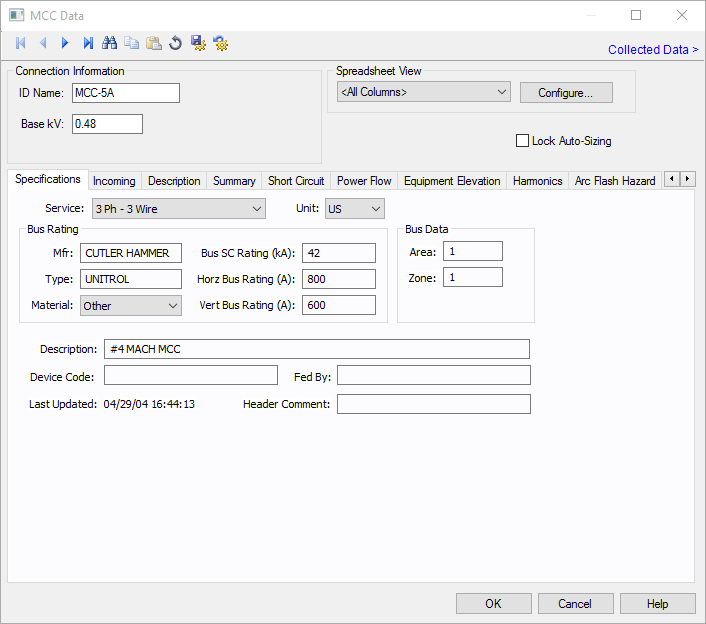
Figure 1: MCC Data Dialog Box
Connection Information
| Option | Description |
|---|---|
| ID Name |
Uniquely identifies the equipment item. The program automatically assigns a name, but you can change it, if needed. The name can be up to 16 characters long. For MCCs, the program automatically assigns the names MCC-1, MCC-2, MCC-3, and so on. |
| Base kV | The base kV of the MCC. MCC’s are modeled like a bus in many ways. You can connect cables, busways or transformers to it, and perform fault calculations. |
| Spreadsheet View and Configure | See Configuring the Spreadsheet View for information about these options. |
| Lock Auto-Sizing | When this check box is selected, this item cannot be automatically sized using SmartDesign™ (the auto-design feature). |
Specifications Tab
These are the specifications for the MCC including the bus.
Incoming Tab
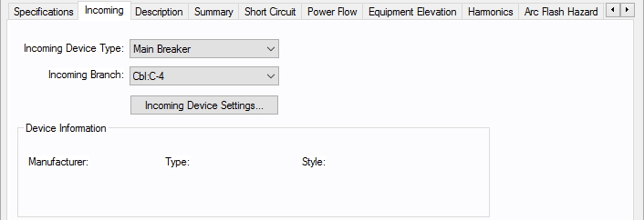
Figure 2: Incoming Tab
| Option | Description |
|---|---|
| Incoming Device Type |
You can select the type of incoming protective device type for the MCC. The choices available are:
|
| Incoming Branch | Select the incoming branch equipment such as cables, transformers or busways. All the branches connected to the MCC in the one-line are displayed. |
| Incoming Device Settings | Opens the data dialog for the main fuse or main breaker specified as the incoming device type. See Low Voltage Breaker Data or Fused Switch Data for more information. |
Description Tab
This is a spreadsheet listing similar to the Device Library. When you place a new MCC on the one-line, the first time you open its database dialog and click on the Description tab, EasyPower displays the MCC Spreadsheet Creation Wizard which enables you to select the number of rows you want. Clear the check box at the bottom of the Wizard dialog if you don't want it to appear with each new MCC. You can insert or append new rows in the spreadsheet if you need them later.
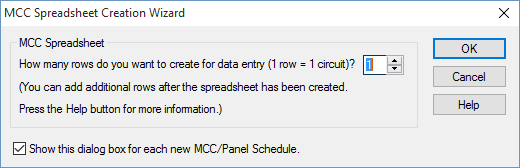
Figure 3: MCC Spreadsheet Creation Wizard Dialog Box
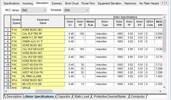
Figure 4: Description Tab of MCC Data Dialog Box
When you click on the Description tab, additional buttons become available on the toolbar. These enable you to perform actions related to the spreadsheet. See Additional MCC and Panel Spreadsheet Options for more information.
| Option | Description |
|---|---|
| MCC Library |
The list contains all of the same schedules as the Device Library. To enter a listing other than those contained in the list, create a new page in the MCC section of the Device Library. See EasyPower Device Library for more information. |
| Schedule | This list enables you to specify which Device Library Schedule your chosen Library Load spreadsheet is located in. To enter a listing other than those contained in the list, create a new page in the MCC section of the Device Library. See EasyPower Device Library for more information. |
| Export | The spreadsheets can be exported to metafiles (.WMF) or delimited database text files (.CSV). Export is beside the Print button on the MCC/Panel dialog box toolbar when the viewing the Description tab. |
Spreadsheet
Note: The Section Space and Equipment Name are not necessary for calculation purposes but are used to match the way they are organized in the MCC.
| Option | Description |
|---|---|
| Section Space | Enter the location of the individual bucket in the MCC. Typical entries would be 1A, 1B, 2A, 2B, 2C, and so on. |
| Equipment Name | Enables you to identify each piece of equipment. |
| Library Load | This list corresponds directly to the Library Load column in the Device Library. After you have made selections in the MCC Library, Schedule and Library Load fields, all of the data cells that follow are automatically filled in when you click on another cell. You can also double-click on the cell to enter something different than what is listed. |
| Status | The third column is a toggle "On/Off" to indicate if this particular item is currently connected to the MCC schedule. This affects the power flow and short circuit current contribution. |
| Load Type |
You can select different kinds of loads such as motors, loads, or sub-MCC/panel. Based on the load type selected, various analysis are possible. When you select a load type, the cells in the row that do not apply become unavailable. You might see a Data button indicating you need to enter data specific to the load type. Cells highlighted in red require data in order to perform any analysis. The following load types are available:
Note: Motor FLA for 3-phase motors is calculated as follows. For U.S. units, the NEC table FLA values are used. For metric units, motor FLA is calculated as Motor kW/(Motor Eff * Motor power factor * Equipment kV * SQRT3). |
The rest of the fields correspond directly to those in the Device Library. See EasyPower Device Library for more information.
For more information on the MCC spreadsheet, see the following topics:
-
For information on how to configure the columns that appear in the spreadsheet view, see Configuring the Spreadsheet View.
-
For information on exporting schedules, see Exporting an MCC or Panel Schedule. The spreadsheets can be exported to metafiles (.WMF) and delimited database text files (.CSV).
- For notes on MCC spreadsheets, see MCC Spreadsheet Notes.
Summary Tab
The Summary tab of MCC Data dialog box provides the total load on the MCC and the load that must be used in designing.
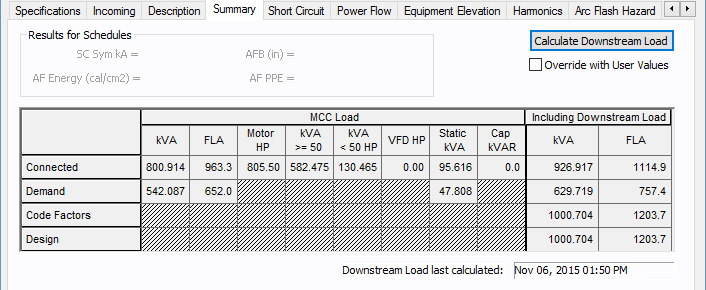
Figure 5: Summary tab of MCC Data Dialog Box (U.S. Units)
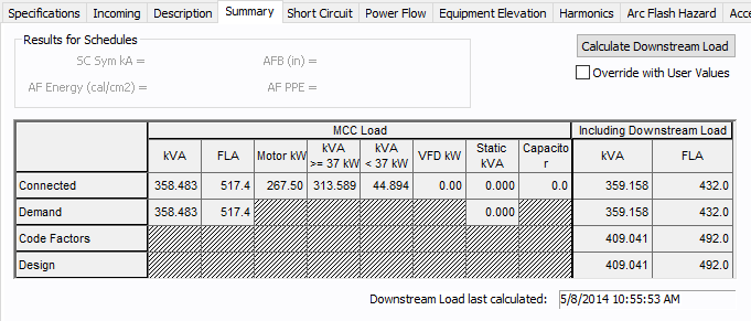
Figure 6: Summary tab of MCC Data Dialog Box (Metric Units)
| Option | Description |
|---|---|
| Calculate Downstream Load | Calculates the total load on the MCC, taking into account the connected load, demand factors, and NEC code factors. |
| Override with User Values | This check box enables you to enter data in the Total Downstream Load – kVA column. |
Spreadsheet
The spreadsheet has two sections – MCC Load and Including Downstream Load.
| Option | Description |
|---|---|
|
MCC Load This spreadsheet section provides the summary of the loads fed by the feeders of the MCC. The loads from the sub-MCC and sub-panels are not included in this section. |
|
| Total kVA | This is the aggregate load. |
| Total FLA | Total load in amps. |
| Motor HP | The total HP for the items with "On" in the Status column of the Description section. |
|
Motor kVA >= 50 HP Motor kVA >= 37 kW |
The total KVA for connected items equal to or greater than 50HP (U.S. units) or 37 kW (metric units). |
|
Motor kVA < 50 HP Motor kVA < 37 kW |
The total KVA for connected items greater than 50HP (U.S. units) or 37 kW (metric units). |
|
VFD HP or kW |
Variable frequency drive HP (U.S. units) or kW (metric units). |
| Static kVA | Total kVA of the loads. |
| Capacitor kVAR | Total kVARs of all the capacitors |
| (Calculations) | |
| Connected | Connected kVA = [(SkW)2 + (SkVAR)2]1/2 |
| Demand |
Demand kVA = [S(kW * DF)2 + S(kVAR * DF)2] ½ Where DF is the individual demand factor of each MCC circuit. |
| Code Factors |
Code Factors kVA = [(kWL + SkW)2 + (kVARL + SkVAR)2]1/2 Where, kWL = Code Mult Factor * kW for largest motor in MCC. KVARL = Code Mult Factor * kVAR for largest motor in MCC. kW and kVAR are for the rest of the loads. The code multiplying factor is specified in Tools > Options > Equipment. |
| Design |
Design kVA = Code Factors kVA * Design Factor The Design Factor is specified in Tools > Options > Equipment. |
|
Including Downstream Load This provides the sum of the loads fed by feeders inside the MCC and the sub-MCC and sub-panels. |
|
| kVA | Total kVA load calculated. You can enter your own values in these fields by selecting the check box for Override with User Values. |
| FLA | Total FLA load calculated. You can enter your own values in these fields by selecting the check box for Override with User Values. |
Short Circuit Tab
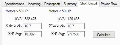
Figure 7: Short Circuit Tab of MCC Data Dialog Box (U.S.)
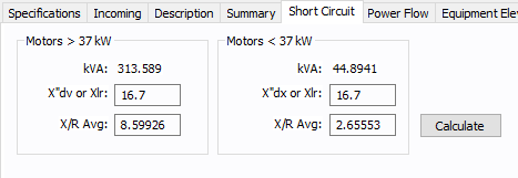
Figure 8: Short Circuit Tab of MCC Data Dialog Box (Metric)
| Option | Description |
|---|---|
|
kVA >50Hp kVA >37kW |
Total kVA of the motors which are greater than 50Hp (U.S. units) or 37kW (metric units). |
| X"dv or Xlr | Is set at the default value for >50Hp (U.S. units) or 37kW (metric units). You can enter your own value and it applies to all the motors greater than 50Hp or 37kW. |
| X/R Avg | Calculate fills this field using values from the spreadsheet. You can enter your own X/R average. |
|
KVA <50Hp kVA >37kW |
Total kVA of the motors which are less than 50Hp (U.S. units) or 37kW (metric units). |
| X"dx or Xlr | Is set at the default value for <50Hp (U.S. units) or 37 kW (metric units) but you can change this. You can enter your own value and it applies to all the motors less than 50Hp or 37kW. |
| X/R Avg | Calculate fills this field using values from the spreadsheet. You may enter your own X/R average. |
| Calculate | Click to calculate the X/R averages for motors greater than and less than 50Hp (U.S units) or 37kW (metric units). |
Power Flow Tab
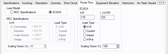
Figure 9: Power Flow Tab of MCC Data Dialog Box
Equipment Elevation Tab
See MCC Elevation for information about this tab.
Harmonics Tab
Use the Harmonics tab to indicate whether this equipment item is introducing harmonics into your power system.
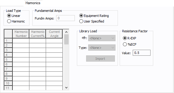
Figure 10: Harmonics Tab
| Option | Description | |||||||||||||||||||||
|---|---|---|---|---|---|---|---|---|---|---|---|---|---|---|---|---|---|---|---|---|---|---|
| Load Type |
The default is Linear, indicating the equipment does not produce harmonics. Choosing Harmonic makes the item an harmonic source and makes other fields in this tab available to edit. Note: For an adjustable frequency drive (AFD), the Load Type is always Harmonic. |
|||||||||||||||||||||
| Fundamental Amps |
Use to set the fundamental amps. The options are as follows:
To use fundamental current calculated by power flow, select Calculated from Power Flow in the Summation Fundamental Voltage area of the Harmonics Options > Control dialog box. |
|||||||||||||||||||||
| Harmonic Spreadsheet |
Use the spreadsheet to enter the harmonic spectrum produced by this item. You can enter up to 30 different harmonics in each equipment item. In the spreadsheet, enter the Harmonic Number (such as 5 for the 5th harmonic), the Harmonic Current in percent of the Fundamental Amps, and the Current Angle. By indicating the current angle, you can simulate transformer phase shift effects on rectifiers so appropriate canceling can take place. The harmonic may be integer or non-integer. |
|||||||||||||||||||||
| Library Load |
Common harmonic spectra may be entered from the device library. For instructions on how to enter your own spectra information, see Harmonics with Spectrum™. After selecting a particular device library spectrum from the Mfr and Type lists, click Import, and that spectrum is entered into the harmonic spreadsheet. |
|||||||||||||||||||||
| Resistance Factor |
EasyPower offers two methods for calculating RH:
RH = RFund * H R-EXP RH = RFund * (1+ECF*H2)/(1+ECF) EasyPower defaults all skin effect correction to R-EXP and a value of 0.5.
|
Arc Flash Hazard Tab
EasyPower calculates arc flash risk assessment results using the options set on the Arc Flash Hazard tab. The results are calculated for automatic transfer switches, buses, tool points of connection, MCCs, and panels.
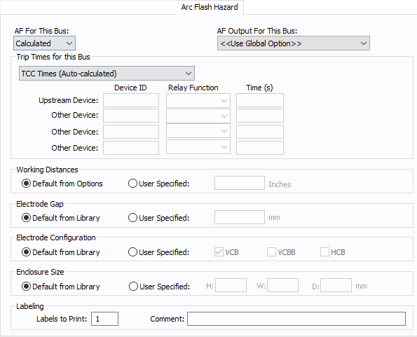
Figure 11: Arc Flash Hazard Tab
| Option | Description |
|---|---|
| AF For This Bus |
You can specify how you would like arc flash results determined for this bus using AF for this Bus. Calculated: When the bus is faulted, EasyPower the performs arc flash hazard analysis using the calculation method specified in Short Circuit Options. EasyPower uses other settings on this tab as part of the calculations. Excluded: Select to exclude the bus from arc flash reports. An example of when you might select this option is for a bus that is required to model the electrical parameters of the system but does not actually represent a piece of electrical equipment. Other applications include nodes and tap-offs (junctions), where energized work is not required. Forced To: When you select this option, you can enter the incident energy and arc flash boundary for this bus. The incident energy and arc flash boundary values are shown on the one-line and in reports and work permits. This can be used for instances where you need to apply a calculation that is outside the scope of the industry standard calculations. |
| AF Output For This Bus |
You can specify whether to display results on the line side or the load side of the Main protective device of the bus equipment. If the arc flash hazards output for this bus needs to be different from the global option, use this field. The choices are:
|
| Trip Times for this Bus |
You can select the method for determining trip times for this bus by choosing from the following:
Note: When a user-defined time is specified and the calculation method is set to use the integrated method, only the upstream device setting is used. The time is considered as the maximum length of the simulation. See The Integrated Method for more information. |
| Working Distances |
You can specify the working distances shown on the one-line and in reports and work permits.
The units displayed are based on the units selected in Arc Flash Hazard Options on the System tab. For inches, the range is 1-1000. For meters, the range is 0.1 to 1000. |
| Electrode Gap |
You can specify the electrode gap shown on the one-line and in reports and work permits.
|
|
Electrode Configuration |
You can specify the electrode configuration shown on the one-line and in reports and work permits.
Electrodes in Enclosures: Electrodes in Open Air: You can select more than one configuration to represent the multiple types of conditions that can occur for the equipment. EasyPower evaluates each configuration and then provides values for the highest incident energy based on the existing electrode configurations. Annex C in the IEEE 1584-2018 standard describes examples where you might use more than one electrode configuration. Tip: To change the electrode configuration for multiple items on the one-line, select the items in the Database Edit focus and then on the Home tab, click Change > AF Bus Electrode Configuration. Electrode configurations are only applicable to the IEEE 1584-2018 standard. For more information, see Electrode Configuration. |
|
Enclosure Size |
You can specify the enclosure size shown on the one-line and in reports and work permits.
The units displayed are based on the units selected in Arc Flash Hazard Options on the System tab. For inches, the range is .01-1000. For millimeters, the range is 0.1 to 25,000. The enclosure dimensions affect arc flash.
|
| Labels to Print |
Enter the number of labels you want to print for arc flash hazard analysis. If you enter "0," no labels will print. |
| Comment |
You can type a comment that appears on the arc flash label when it is printed. For example, you could type a location description for the equipment to assist with label placement. |
Accessories Tab
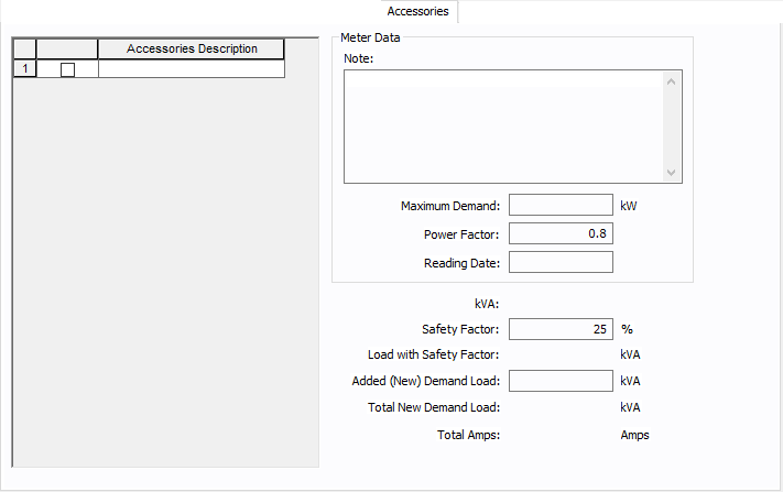
Figure 12: Accessories Tab
| Option | Description |
|---|---|
| Accessories Description | The accessories for distribution equipment types can be specified in the panel, MCC, and bus dialog boxes. You can add or delete the accessory items as needed per equipment. Only the selected items are displayed in the schedule outputs. |
| Meter Data | |
| Note | An accessory note of up to 1,024 characters. |
| Maximum Demand | The maximum demand load at this equipment. |
| Power Factor | The power factor for the equipment. |
| Reading Date | The date the meter was read or the information was gathered. |
| kVA | |
| Safety Factor | Percentage above the kVA that will be multiplied to calculate the new safety factor load. |
| Load with Safety Factor | Load amount after calculating the safety factor. |
| Added (New) Demand Load | User-specified load amount to add to the equipment. |
| Total New Demand Load | Total of the load with safety factor and the added demand load. |
| Total Amps | Amps based on the total demand load. |
Other Tabs
See Common Tabs for information on the Location, Reliability, Comments, Hyperlinks, Media Gallery, or Collected Data tabs.
More Information
| Database Technical Reference | Common Tabs |
| Media Gallery | MCC Spreadsheet Notes |