LV Breaker - Phase Trip Tab
The Phase Trip tab stores data which determine the TCC curves of the device for phase currents. Pickup and delay settings for long time, thermal, short time, and instantaneous trip of the device are selected here. The fields and contents that appear on the dialog box depend upon the type of trip unit selected on the Specifications tab.
Phase Trip for Thermal Magnetic
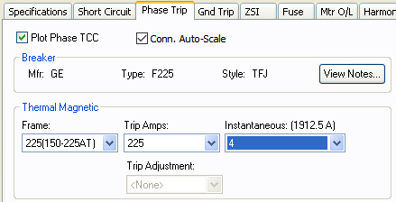
Figure 1: Phase Trip Dialog Box for Thermal Magnetic
| Option | Description |
|---|---|
|
This option is only available after you set the Trip and Solid State Trip fields on the Specifications tab. You can also select or clear it in the Temporary Thermal Magnetic Data dialog box in Coordination mode to avoid plotting the TCC. |
|
|
Conn. Auto-Scale |
When this check box is selected, the program automatically scales the TCC curves based on the phase connection type. Traditionally, for 3PH curves in a TCC, scaling the curves based on the reference voltage is adequate. If a line-to-neutral connected 1PH device is to be plotted with an upstream 3PH device, then the LN connected 1PH curve needs to be shifted by a factor of the SQRT(3) in addition to the voltage-based scaling. Similarly, if a line-to-neutral connected 1PH device is to be plotted with an upstream 1PH-3W device, then the LN connected 1PH curve needs to be shifted by a factor of the 2 in addition to the voltage-based scaling. When the check box is not selected, scaling based on the phase connection type is not applied. The check box status for individually stored TCC plots can be different. The default for new TCC plots is obtained from the database for the device.
|
|
Breaker |
This message shows the manufacturer (Mfr), Type and Style of low voltage breaker that was selected. |
|
View Notes |
Click to view notes recorded in the library for the device. Information may include data sheets or manufacturer's information for the device or assumptions needed to model the device. |
|
Frame description. This may be the frame size, the largest rating in the range of similar models, or a range of sizes that have similar curves. |
|
|
Nominal rated amps the device is rated to carry without tripping. |
|
|
Instantaneous |
Nominal instantaneous trip amps, multiple, or pickup setting. When you highlight or select a choice, the corresponding trip amps appear in parenthesis. |
Phase Trip for Solid State Trip
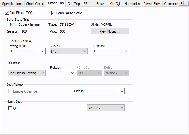
Figure 2: Phase Trip dialog box for Solid State Trip
Phase Trip for Non-Solid State Trip
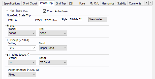
Figure 4: Phase Trip Tab for Non-Solid State Trip
| Option | Description |
|---|---|
|
This check box is only available if the Trip and Solid State Trip settings are selected on the Specifications tab. You can also select or clear it in the Temporary Thermal Magnetic Data dialog box in coordination mode to avoid plotting the TCC. |
|
|
Conn. Auto-Scale |
When this check box is selected, the program automatically scales the TCC curves based on the phase connection type. Traditionally, for 3PH curves in a TCC, scaling the curves based on the reference voltage is adequate. If a line-to-neutral connected 1PH device is to be plotted with an upstream 3PH device, then the LN connected 1PH curve needs to be shifted by a factor of the SQRT(3) in addition to the voltage-based scaling. Similarly, if a line-to-neutral connected 1PH device is to be plotted with an upstream 1PH-3W device, then the LN connected 1PH curve needs to be shifted by a factor of the 2 in addition to the voltage-based scaling. When the check box is not selected, scaling based on the phase connection type is not applied. The check box status for individually stored TCC plots can be different. The default for new TCC plots is obtained from the database for the device. |
|
Non-Solid State Trip |
This message shows the kind of trip unit selected and other descriptions of the device selected in the Specifications tab such as the manufacturer (Mfr), Type and Style of low voltage circuit breaker. |
|
View Notes |
Click to view notes recorded in the library for the device. Information may include data sheets or manufacturer's information for the device or assumptions needed to model the device. |
|
Frame and Trip descriptions.
|
|
|
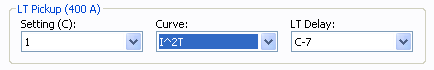
The long time pickup and delay are selected in this section. After the settings are selected, the actual pickup in amperes appears in parentheses. |
|
|
Short time pickup and delay settings. This section is applicable to only devices with short time trip. After the settings are selected, the actual pickup in amperes appears in parentheses.
|
|
|
The instantaneous pickup setting, which is a multiple of long time pickup. When you highlight or select a choice, the corresponding trip amps appear in parenthesis. |
More Information
- Low Voltage Breaker Data
- Database Dialog Box Toolbar
- LV Breaker - Connection Information
- LV Breaker - Specifications Tab
- LV Breaker - Short Circuit Tab
- Ground Trip Tab
- LV Breaker - ZSI Tab
- LV Breaker - Fuse Tab
- LV Breaker - Mtr O/L (Motor Overload) Tab
- LV Breaker - Harmonics Tab
- LV Breaker - Stability Tab
- LV Breaker - Reliability Tab
- LV Breaker - Comments Tab
- LV Breaker - Hyperlinks Tab
- LV Breaker - Collected Data Tab
- LV Breaker - Media Gallery Tab