LV Breaker - Short Circuit Tab
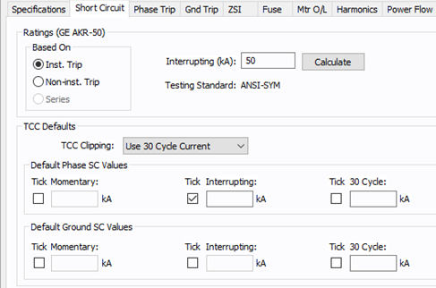
Figure 1: Short Circuit Dialog Box (ANSI)
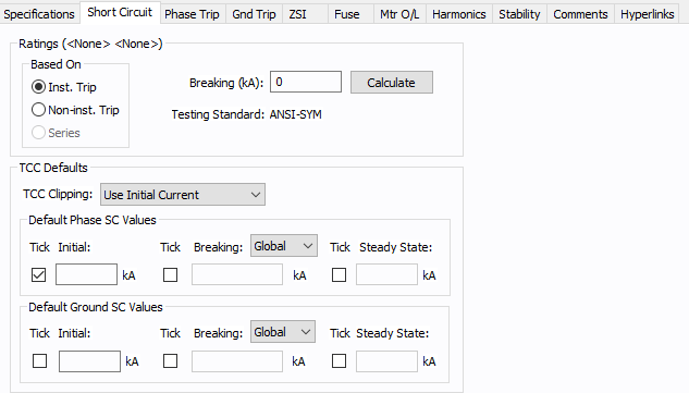
Figure 2: Short Circuit Dialog Box (IEC)
| Option | Description |
|---|---|
|
In many cases, the type of trip or the application of the breaker determines the interrupting current of the breaker. Older (pre-1964) low voltage power circuit breakers with instantaneous trips typically have higher interrupting ratings than the same device without instantaneous trips. The LVPCB device library allows instantaneous and non-instantaneous trip ratings. All ICCB and MCCB breakers are equipped with instantaneous trips. The old cascade application for LVPCBs is not supported in this library. However, you can determine this rating and enter the value directly into the Interrupting kA field. Recent standards allow ICCBs and MCCBs to be rated for series application. This provides increased interrupting kA for some devices. The ICCB and MCCB device libraries allow instantaneous and series rated trip ratings. |
|
|
The interrupting rating of the breaker (for ANSI) or breaking rating (for IEC). |
|
|
Calculate |
Fills in a computed value for the Interrupting kA field, based on the device library entry for Mfr, Type, Style and the base kV. (The Interrupting kA value is based on the breaker multi-pole rating at the 480 volt level.) You can override interrupting kA by typing in different numbers. This button also causes the appropriate Testing Standard to be displayed for your information. (The Testing Standard comes directly from the device library and cannot be changed.) Calculation of series ratings: When you calculate the Interrupting kA based on Series Rating, you will first need to define the upstream breaker Mfr, Type and Style. If the library has the series rating data, then the data is imported from the library. If not, the fully rated instantaneous trip value is used. |
|
Testing Standard |
The standard to which the device complies for testing procedure. |
|
TCC Defaults |
Data entered in this section is used to place tick marks representing short circuit values on the TCC plot. |
|
TCC Clipping |
You can clip the time current curve (TCC) for the breaker at the specified current in kA for Momentary (1/2 cycle), 5-cycle or 30-cycle for ANSI or Initial, Breaking, or Steady State for IEC. Select <None> to avoid clipping of TCC. |
|
Select the appropriate boxes to display the tick mark on the TCC plot.
Enter the corresponding short circuit values in kA in their respective edit fields for phase short circuit and ground short circuit. |
|
|
Default Phase SC Values |
The values in kA, entered in these fields can be displayed for phase currents on TCC plots. |
|
Default Ground SC Values |
The values in kA, entered in these fields can be displayed for ground currents on TCC plots. Ground SC values section is applicable only for solid state trip units with ground fault trip. |
More Information
- Low Voltage Breaker Data
- Database Dialog Box Toolbar
- LV Breaker - Connection Information
- LV Breaker - Specifications Tab
- LV Breaker - Phase Trip Tab
- Ground Trip Tab
- LV Breaker - ZSI Tab
- LV Breaker - Fuse Tab
- LV Breaker - Mtr O/L (Motor Overload) Tab
- LV Breaker - Harmonics Tab
- LV Breaker - Stability Tab
- LV Breaker - Reliability Tab
- LV Breaker - Comments Tab
- LV Breaker - Hyperlinks Tab
- LV Breaker - Collected Data Tab
- LV Breaker - Media Gallery Tab