Control Tab
To set short circuit options, from the Short Circuit focus, click SC Options. You can also access the options from within the Database Edit focus by selecting Tools > Options > Analysis Options > Short Circuit.
On the Control tab, specify the options you want for controlling the behavior of a short circuit study.
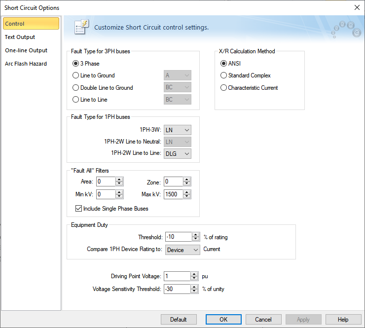
Figure 1: Control Tab of the Short Circuit Options Dialog Box
| Option | Description |
|---|---|
|
For 3-phase faults, there are four different types of faults available during a short circuit analysis. The default is 3 Phase which is generally used to determine the highest available currents for equipment duty comparisons, and relaying. The other types, Line to Ground, Double Line to Ground, and Line to Line are generally used for specialized relaying applications or system troubleshooting. You can specify the phases to fault for each fault type. During short circuit analysis, the program automatically changes the display phases if the phases selected appear on the one-line do not match these fault values. Note: Your phase descriptions may be different than described here if they have been customized in Tools > Options > Terminology. |
|
|
Fault Type for 1PH buses |
For single-phase faults, there are three different types of faults available during a short circuit analysis. You can specify the phases to fault for each fault type. The options are as follows:
|
|
Short circuit calculations are based on one of three methods:
IDC = Ö2 IAC RMS SYM exp (-p /|X/R|) After each DC component is determined and totaled, the equivalent X/R ratio is found from the equation below. Equivalent X/R = -p/ ln (S IDC / S IAC RMS SYM / Ö2) Reference: |
|
|
Enables you to specify a specific bus Area, Zone, and kV Range that to fault and report when you fault multiple or all buses. This type of analysis is useful when you are interested in studying only a specific region and do not need all of the output associated with a full system analysis. This method is common for old-style text programs. In EasyPower, it is just as simple to select the buses you wish to fault from the one-line fault buses. Only the selected buses are faulted. |
|
|
System fault point voltage in per-unit. This value defaults to 1.0 per-unit. |
|
|
Include Single Phase Buses |
Selects whether single-phase buses are included when bus faults are performed. By default, this option is selected. |
|
Sets the lower limit for flagging breaker violations in SmartDuty™. If the threshold is set to -10 percent, SmartDuty™ will flag all equipment which has short circuit duties within 10 percent of their maximum rating (greater than 90% of their rating). Note: The ability to automatically check equipment duties during analysis is only available if you have purchased the SmartDuty™ option to EasyPower. For example, a GE AM-13.8-500 air blast breaker has a momentary and interrupting duty rating of 19.56/37 kA at 13.8 kV. SmartDuty™ provides a warning flag if the current exceeds 17.6/33.3 kA in either the momentary or interrupting rating. If the current exceeds 19.56/37 kA, a violation is flagged. Note: You must click |
|
|
Voltage Sensitivity Threshold |
Sets the lower limit setting for flagging voltage violations. If the threshold is set to -30 percent, bus voltages lower than 30 percent (70 percent voltage) of the bus' base kV is flagged. This enables you to quickly check for motor contactor dropout, lighting flicker, and so on. Note: For this field to have any effect, you must select one or more of the Voltage Sensitivity check boxes in the One-line Output or the Text Output tab of the Short Circuit Options dialog box. |
|
Compare 1PH Device Rating to Device/Bus Current |
For more information, see Equipment Duty for Single-Phase Devices. |
|
Default |
In the Short Circuit Options Defaults dialog box, you can specify which default short circuit option settings you want to use. This affects the settings in the entire dialog box and is not limited to only the currently selected tab. These default settings are used for all new one-lines. The options are:
Default settings specified here only affect ANSI settings. |
