This topic describes new EasyPower features and enhancements, security improvements, and bug fixes that are included in the release.
Features and Enhancements
Store Short Circuit and Arc Flash Analysis Results in the Database
-
Store Short Circuit and Arc Flash Results to Quickly Generate Reports
-
Display Short Circuit and Arc Flash Results in the Reports or Browser
-
Display the Arc Flash Calculation Method in Reports and Arc Flash Labels
-
Arc Flash Schedule Variables Now Display Units Based on Arc Flash Hazard Settings
-
Set Default for the "Use 100% Convention for Displaying Analysis Overloads/Overduties" Option
Scenario Manager - Store Short Circuit and Arc Flash Analysis Results
Database Browser and Report Enhancements
-
Notes Added to the Configuration File Can Be Included in Reports
-
Test Standard Columns Added to the Database Browser and Reports
Improved Access to Analysis Options
One-line Text Template Improvements
Note: New release features often include changes to the database. This may affect what you see in the Database Browser and also what is included when you export data into CSV files. If your existing work processes rely on information from the database, be sure to review your processes after you update your software.
Store Short Circuit and Arc Flash Analysis Results in the Database
Store Short Circuit and Arc Flash Results to Quickly Generate Reports
You can now store short circuit and arc flash analysis results in your one-line database. A new menu below the Short Circuit button has additional options for you to store or clear results. You can quickly generate and store a wide variety of results for various short circuit and arc flash parameters in the database.
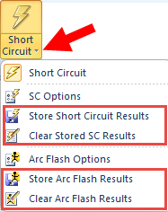
Figure 1: Store Options for Short Circuit and Arc Flash
Display Short Circuit and Arc Flash Results in the Reports or Browser
New report configurations are available so that you can create typical analysis reports with the stored results. You can use the configurations we provide or use them as templates to create your own custom configurations.
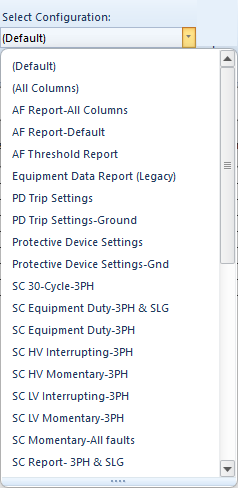
Figure 2: New Configurations for Stored Arc Flash, Short Circuit and Equipment Duty Results
The same configuration file can be used for either the Database Report or the Database Browser.
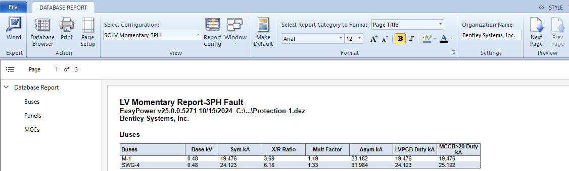
Figure 3: LV Momentary Report for 3-Phase Faults (Based on the Selected Configuration)
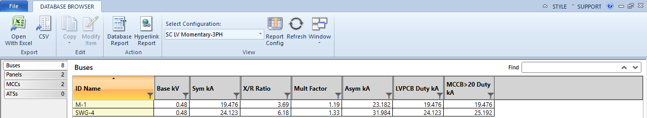
Figure 4: 3-Phase LV Momentary Fault Results in the Database Browser (Based on the Selected Configuration)
Display Stored Results on the One-Line
You can use one-line text templates to display the stored results on the one-line. The one-line text templates are now easily accessible from the Home menu while you are in the Database Edit focus, enabling you to quickly and easily display different data text blocks on your one-line diagrams.
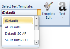
Figure 5: Text Templates Display Short Circuit and Arc Flash Results
You can use the text templates we provide or use them to create your own text templates.
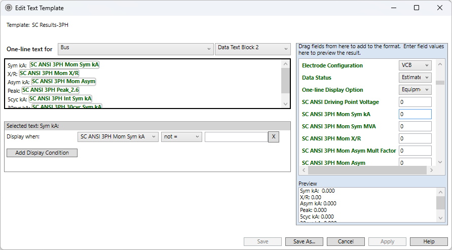
Figure 6: Edit Text Templates Dialog Box
See One-line Text Template Improvements for additional information.
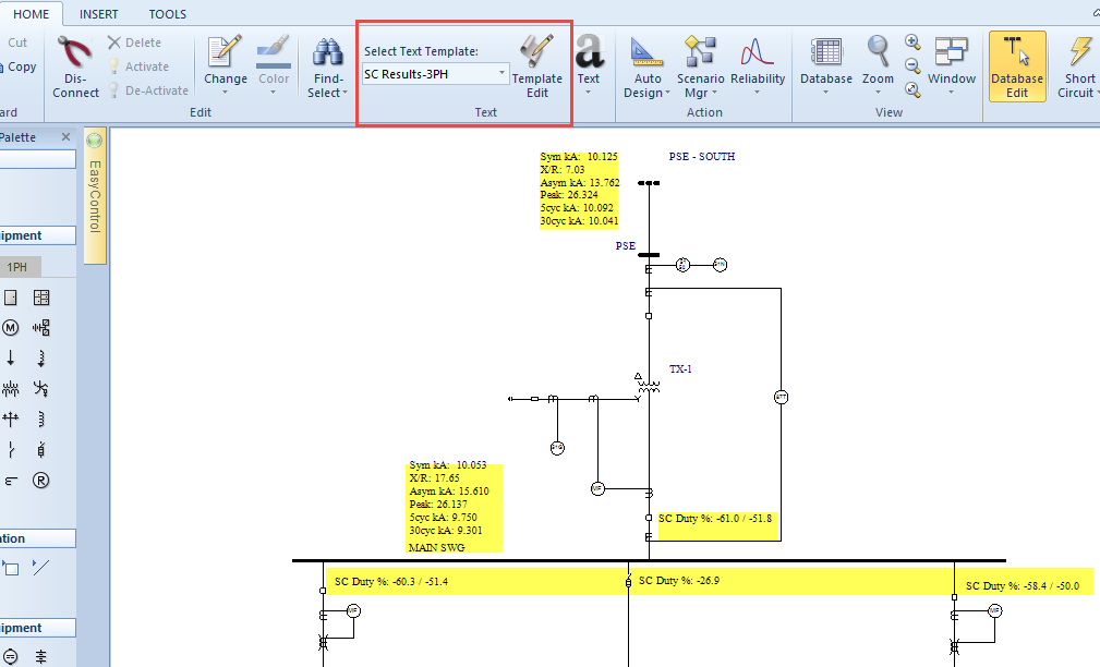
Figure 7: 3-Phase Short Circuit Results are Displayed on the One-line in the Database Focus (Based on the Selected One-line Text Template)
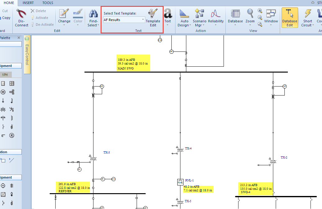
Figure 8: Arc Flash Results are Displayed on the One-line in the Database Focus (Based on the Selected One-line Text Template)
Display the Arc Flash Calculation Method in Reports and Arc Flash Labels
There is a new column available for arc flash reports that displays the arc flash calculation method used for each bus. You can add this column to your custom report configurations.
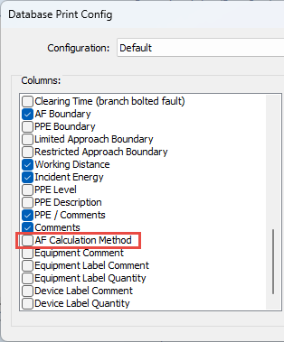
Figure 9: The Arc Flash Calculation Method Can Be Added to Report Configurations
You can also add the arc flash calculation method to arc flash labels in the Label Designer.
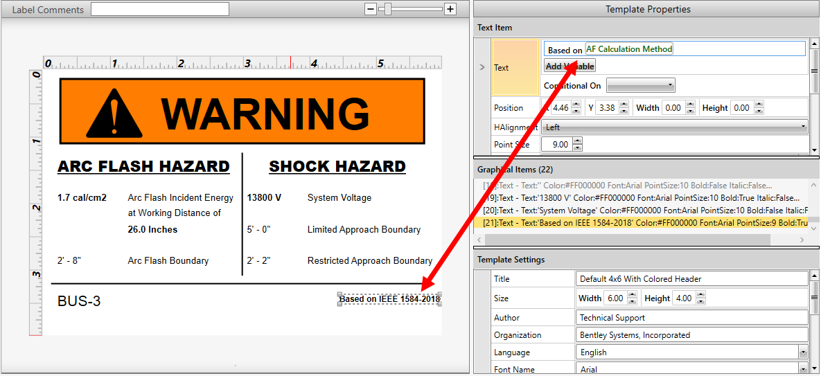
Figure 10: Arc Flash Label with the Arc Flash Calculation Method Added in the Label Designer
For more details about how the values for this field are determined, see AF Calculation Method.
Advanced Query to Select kV Range and Bus Type
There are new query options for kV Range and Bus Type available on the Advanced tab of the Query dialog box. You could use this to select high voltage open air buses quickly and to perform just the single line-to-ground faults on those buses, for example.
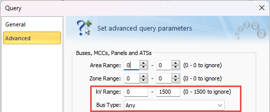
Figure 11: New Options for kV Range and Bus Type
Arc Flash Schedule Variables Now Display Units Based on Arc Flash Hazard Settings
Several schedule variables for arc flash results have been renamed and now use the units set up in the Arc Flash Hazard settings to ensure consistency with the Database Browser and one-line text templates.
|
Old Variable Name |
New Variable Name |
|---|---|
| %afh_boundary% | %AFBoundary% |
| %afh_incident_energy% | %AFIncidentEnergy% |
| %afh_ppe% | %AFPPELevel% |
| %afh_working_distance% | %AFWorkingDistance% |
Existing schedules that used the old variables will now use the new variables to retrieve the values, but continue to display the original units.
Arc Flash Report Columns Renamed
Several columns in reports related to the trip device for arc flash have been renamed to reduce confusion, since the device that is being referred to is not always immediately upstream, as the name would seem to indicate.
Arc Flash Hazard Report
-
Upstream Trip Device Name is now Trip Device Name.
-
Upstream Bus Name is now Trip Device Bus Name.
-
Upstream Function Id is now Trip Device Function ID.
-
Upstream Trip Device Function is now Trip Device Function.
Arc Flash Incident Energy Threshold Report
-
Upstream Trip Device is now Trip Device.
Scenario Comparison Report
- Upstream Trip Device Name is now Trip Device Name.
-
Upstream Bus Name is now Trip Device Bus Name.
-
Upstream Trip Device Function is now Trip Device Function.
Label Designer
- Upstream Bus Name is now Trip Device Bus Name.
-
Upstream Trip Device is now Trip Device Name.
Set Default for the "Use 100% Convention for Displaying Analysis Overloads/Overduties" Option
In the system Options dialog box, after you select or clear the checkbox for the Use 100% convention for displaying analysis overloads/overduties option, you can use Set Default to save your selection as the default value for all new one-lines. This stores the setting in the file with the project.
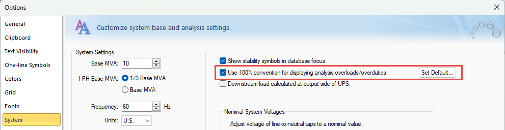
Figure 12: The 100% Convention Checkbox with the Corresponding Set Default Button
Additional Information
Due to the improvements with this feature, the Advanced menu under the Fault Bus(es) button has been removed for ANSI systems. The menu remains in place for IEC systems.
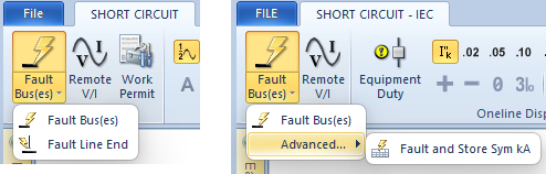
Figure 13: ANSI and IEC Fault Bus(es) Menus
The stored values continue to be displayed in the Bus Data dialog box on the Switchgear/Switchboard/Panelboard tab, in panels and MCCs on the Summary tab, and for ATS equipment on the Specifications tab.
The results are stored with the session but are not saved with the database until you either save the file or select to save temporary changes when switching the focus.
See Store Short Circuit Results and Store Arc Flash Results for more information.
Scenario Manager - Store Short Circuit and Arc Flash Analysis Results
Store Short Circuit and Arc Flash Analysis Results
While in a scenario, you can fault and store short circuit and arc flash results just as you can in the Base Case.
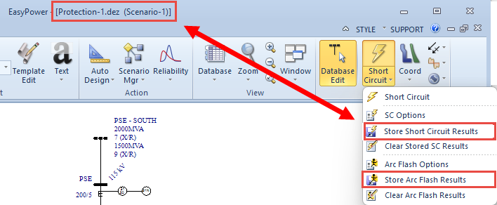
Figure 14: Fault and Store Options for Short Circuit and Arc Flash
Store Worst Case Arc Flash Results
After running the Scenario Comparison Report, you now have the option to store the worst case arc flash results for each bus, MCC, panel, or ATS in the report. These are displayed in the equipment data dialog boxes on the Panelboard, Switchboard, or Switchgear tab of a bus, the Summary tab of a panel or MCC, and the Specifications tab of an ATS. These results are also available to include in the Database Browser and Database Report configurations, in schedules, and in custom one-line text templates.
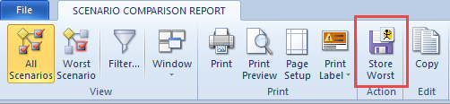
Figure 15: The Store Worst Button on the Scenario Comparison Report
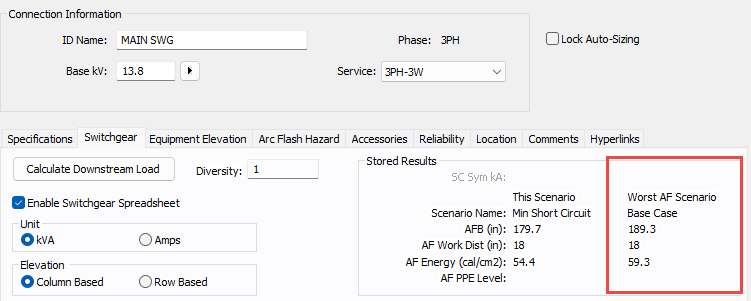
Figure 16: The Worst Arc Flash Scenario Results for a Switchgear Bus
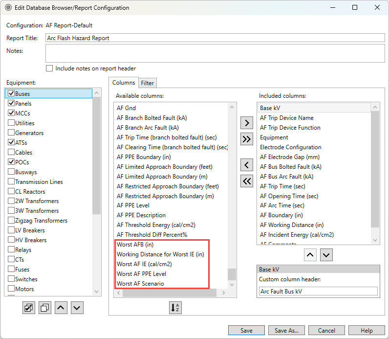
Figure 17: Worst Case Columns Available for Database Browser and Report Configurations
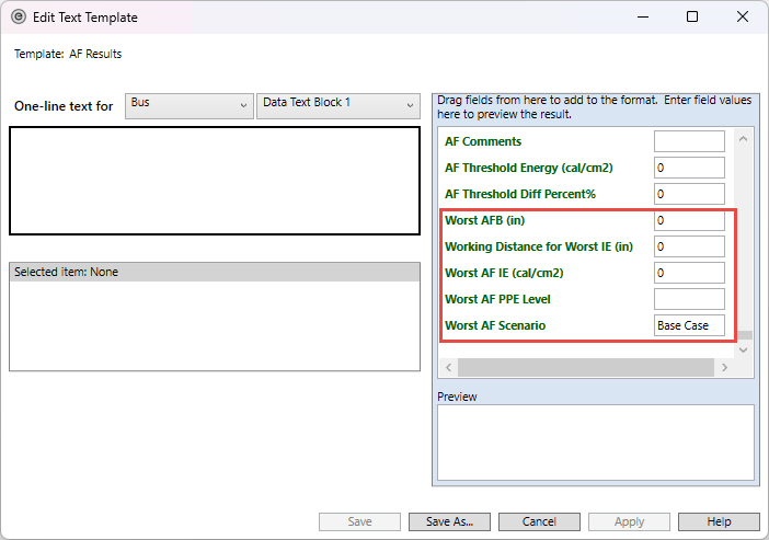
Figure 18: Worst Arc Flash Results Fields on the Text Template
New Schedule Variables for Worst Case Arc Flash Results
There are new schedule variables for the worst case arc flash results that you can add to your schedules. These include:
-
%AFWorstBoundary%
-
%AFWorstIncidentEnergy%
-
%AFWorstPPELevel%
-
%AFWorstWorkingDistance%
-
%AFWorstScenario%
Clear Worst Case Arc Flash Results
There is a new option when viewing the Base Case to clear the worst case arc flash results that were previously stored. This clears the results for the selected equipment or for all applicable equipment if nothing is selected.
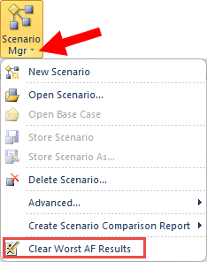
Figure 19: Clear Worst Arc Flash Results Option
Database Browser and Report Enhancements
Customize Report Column Names for Configuration Files
When you create a configuration file for the Database Browser or Database Report, you can now create customized column header names for the report columns.
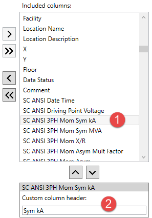
The custom column headers are specific to the configuration. Each configuration can have a different custom column header for the same column name.
Specify Report Configuration File Locations
You can specify the file location of your report configurations in Tools > Options > File Locations.
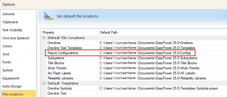
Figure 20: Report Configuration File Locations
Report Title is Used as the Configuration File Name
When you create a configuration file for the Database Browser or Database Report, you have the option to specify a Report Title. If you enter a title, that text is used as the default file name for the configuration file. You can still change the name if you want something different. This saves you time when creating a new configuration file.
The title can be up to 125 characters in length.
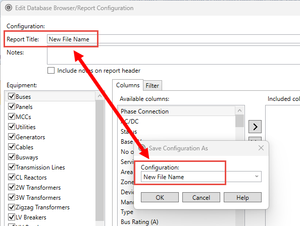
Figure 21: The Report Title is Used as the Default Configuration File Name
Notes Added to the Configuration File Can Be Included in Reports
There is a new Notes box for the Database Browser and Report configuration file. If you select the Include notes on report header checkbox, the first two lines of the note are shown in the header of the report output or when exporting to Excel.
The note can be up to 250 characters in length.
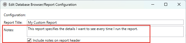
Figure 22: Notes and the Related Checkbox for the Configuration File
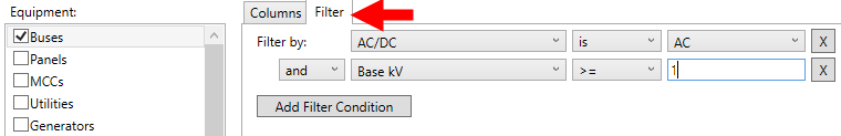
Use Filters to Modify the Results Displayed
You can create filters for equipment items in the configuration file. After selecting an equipment item, click the Filter tab, and then specify the Filter by criteria. You can use Add Filter Condition to apply additional filters to the equipment.
You could use this, for example, to create separate reports for low voltage and high voltage equipment, or for AC or DC equipment. The filters are saved with the configuration.
When equipment items are modified, added, or deleted, the filter and sort order are reapplied to items that appear in the Database Browser. Note that this works differently in the Database Report. Changes are not reflected in the Database Report until a new report is run.
If the changes affect related equipment, the related equipment is not updated automatically, but you can use the Refresh button (or F5) in the Database Browser to update the related items.
Test Standard Columns Added to the Database Browser and Reports
Several new columns have been added for various equipment items to display the test standard applied.
| Equipment | Columns Added |
|---|---|
| ATS |
Test Standard SC Rating (kA) |
| MCC | Test Standard |
| Panel | Test Standard |
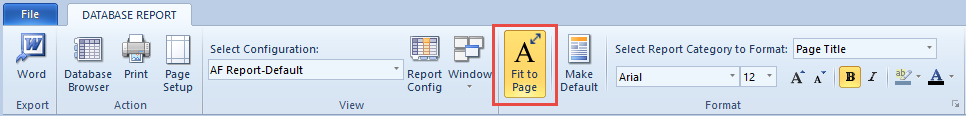
Database Report Fit to Page Option Added
A new Fit to Page option in the Database Report reduces the font size to fit all the columns in the report onto one page.
Database Browser Performance Improvements
We have optimized the performance of the Database Browser to improve the user experience and to prepare for future enhancements.
Improved Access to Analysis Options
Open Analysis Options from Within the Home Tab
While viewing the Home tab in the Database Edit focus, you can now view and edit the analysis options by selecting the arrow below the each of the focus buttons for Short Circuit, Coordination, Power Flow, Harmonics, and Dynamic Stability/Transient Motor Starting.
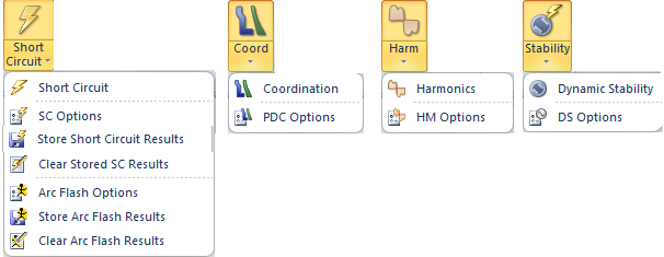
Figure 23: Analysis Options Below Each Option Button
The new options are also available to add to the Quick Access Toolbar.
One-line Text Template Improvements
You can now create, edit, and select one-line text templates from the Home menu. Use text templates to quickly display the exact information you want shown on the one-line.
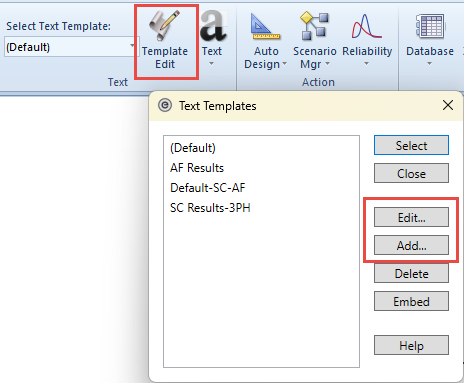
Figure 24: Add or Edit a Text Template
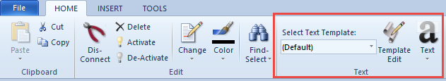
Figure 25: Select Text Template
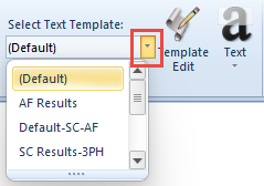
Figure 26: Text Templates.
You can choose to embed a custom template in the one-line so that it is automatically used for everyone who opens the one-line.
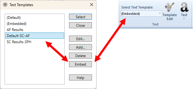
Figure 27: Embedding a Text Template into a One-line
This simplifies the use of text templates and eliminates the need to import and export text template files.
As a result of this improvement, the One-line Text tab has been removed from the System > Options dialog box.
In addition, the file TextTemplate.eztxt has been removed from the installation as it was redundant to the default text template settings. In File Locations, the default One-line Text file is now blank, indicating the default settings are used for new one-lines unless you choose to specify a default one-line text template file.
Short Circuit Enhancements
New Elements-Based Short Circuit Calculation Method
We have replaced the symmetrical components (sequence-based) short circuit calculation method with a new physical elements-based method that produces the same results as the symmetrical components method while also enabling the modeling of unbalanced networks. These efforts will enable us to make significant enhancements in future releases.
Short Circuit Option for Setting Driving Point Voltage
A new method is now available for setting the driving point voltage at individual sources. There are new options in the Short Circuit Options - Control tab for applying driving point voltage. The choices are Faulted bus or Sources. The classical short circuit method described in the ANSI/IEEE guide applies the driving point voltage at the faulted bus. Now, you can apply the driving point voltage to the Thevenin equivalent voltage of all sources to take the source voltage into account.
See figure below.
Short Circuit Option for Including Line Capacitance and Shunts
You can now include line capacitance and shunts in the short circuit calculations. You can include cable and transmission line capacitance and capacitors into the network in short circuit calculations if those options are enabled. This could effectively improve the accuracy of the short circuit solutions in high capacitance networks such as the collector system of a renewable power plant or a cable feed industrial network.
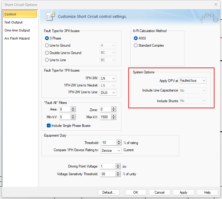
Figure 28: System Options on the Short Circuit Options - Control Tab
See System Options (ANSI) or System Options (IEC) for more information.
Single-Phase Base MVA Option
You can now specify the single-phase base MVA to either be one-third of the system base MVA or equal to the system base MVA. This affects the per-unit calculations for branches that include single-phase cables or transmission lines.
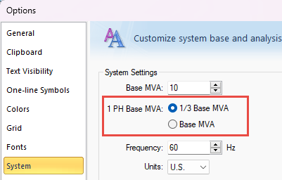
Figure 29: Single-Phase Base MVA Options
Misc. Enhancements
Auto-Calculate Z% for Two-Winding Transformers
There is now an Auto-calculate checkbox to populate the Z%, X/R ratio, grounding impedance, and amp class values on two-winding transformers with typical industry values based on the transformer's characteristics.
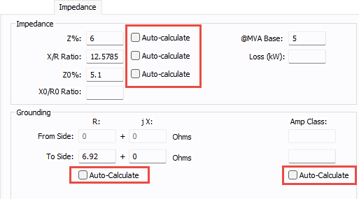
Figure 30: Auto-Calculate Checkboxes on the Impedance Tab of a Two-Winding Transformer
You can set or clear the checkboxes for one or more selected transformers by using the Change options on the Home tab.
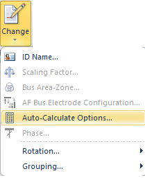
Figure 31: Change Auto-Calculate Options
For additional information, see Z%.
Support for 64-Bit
EasyPower is now a 64-bit application. This improves performance and enables EasyPower to better handle larger files.
Characteristic Current Method Removed
In Short Circuit Options, the X/R calculation method for Characteristic Current has been removed. Any existing one-line file set with this option will now use the ANSI method.
X/R Calculation Removed from TCC Options
The X/R Calculation Method options in the TCC Options dialog box were redundant and have been removed. The program uses the X/R Calculation Method specified in the Short Circuit Options.
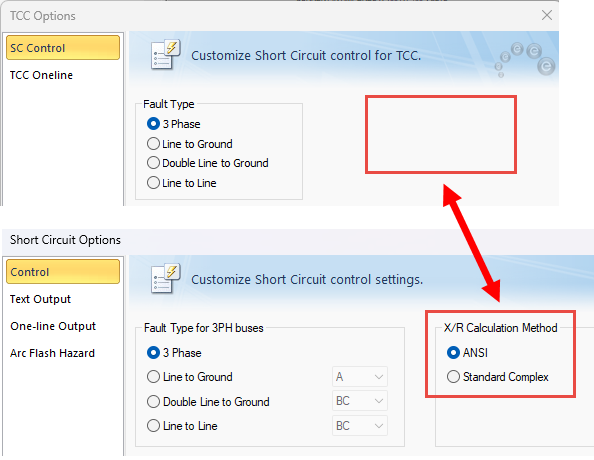
Figure 32: X/R Calculation Removed from TCC Options; Short Circuit Options are Used Instead
Legacy Arc Flash Calculation Methods Removed
On the Arc Flash Hazards tab in the Short Circuit Options dialog box, under Standard, the V6.0 Enhanced and V7.0 Enhanced options have been removed. These were created to cover the gaps in the 2002 edition of the IEEE 1584 standard and are now outdated with the adoption of 1584-2018.
Any existing file with either of these standards selected will be set to the latest IEEE 1584 standard.
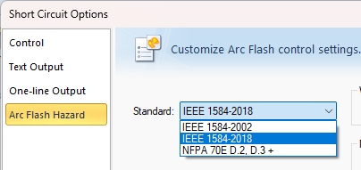
Figure 33: Arc Flash Standards
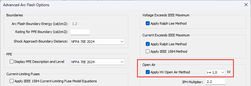
Arc Flash Open Air Method Renamed
In the Advanced Arc Flash Options dialog box, the open air option to Apply NFPA 70E 2009 Annex D.8 is now Apply HV Open Air Method. The method is still based on NFPA 70E 2009 Annex D.8.
Revit Enhancements
Revit® 2025 Support
The EasyPower Integrator for Revit now supports the 2025 version of Autodesk® Revit®. You can download the EasyPower Integrator app from the Autodesk App Store. The App Store will be updated with the latest version shortly after the EasyPower 2025 release, so please verify the version prior to downloading.
Transformer Impedance Uses the Auto-Calculate Value for Revit Imports
When importing transformer information to EasyPower from Revit, if the default for the impedance Z% value is set to auto-calculate and there is no value deliberately set by mapping, EasyPower uses the auto-calculated value to determine the impedance. If there is no mapping and auto-calculate is not selected, the value is left blank.
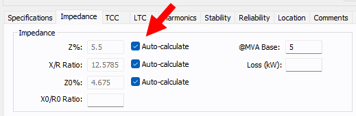
Figure 34: Auto-calculate on the Transformer Data Dialog Box Impedance Tab
Security Improvements
This release includes a number of improvements that strengthen the security of the software.
Bug Fixes
EasyPower 2025 Release Update 3
The following issue has been addressed in EasyPower 2025 Release Update 3 (build 25.0.0.8059):
-
Fixed an issue where custom paths set up in Options > File Locations were removed when the dialog box was opened, and then when the dialog box was reopened, the paths were set to default locations.
EasyPower 2025 Release Update 2
The following issues have been addressed in EasyPower 2025 Release Update 2 (build 25.0.0.8049):
-
Fixed an issue where network printers were not available to select when printing a one-line on a 64-bit Windows system.
-
Fixed an issue where symmetrical fault current in EasyPower was not exported to Revit.
-
Fixed an issue where some of the text in the Chinese version of EasyPower showed unrecognizable characters due to an encoding mismatch.
EasyPower 2025 Release Update
The following issues have been addressed in the EasyPower 2025 Release Update (build 25.0.0.8031):
-
Fixed an issue where installing EasyPower on a computer with 32-bit Microsoft Access would cause the Device Library to fail to open. Now, the installation stops if 32-bit Microsoft Access is present, and the program displays a message indicating you need to upgrade to the 64-bit version.
-
Fixed an issue that occurred when the Windows region setting specified using a comma for a decimal separator instead of a decimal point, resulting in a display issue on the one-line. This has been corrected.
-
Fixed an issue where performing a fault and store of arc flash values did not immediately display the results for some items on the one-line until after an action (such as a pan or zoom) was taken. Now, the results are displayed immediately.
EasyPower 2025 Release
The following issues have been addressed in the EasyPower 2025 Release (build 25.0.0.8014):
Arc Flash
-
Fixed an issue in which arc flash calculations were showing incident energy results in the one-line view but not the arc flash report. This was a case specific to protective devices having incomplete data or the specified device not existing in the device library that was being used.
-
Fixed an issue where the arc flash threshold report with energy in Joules was giving incorrect percent for the difference column.
Change
-
Fixed an issue where using the Change > Auto Calculate command from the ribbon on an MCC would cause the MCC total load to be zero and prevent entry into an analysis focus.
Note: Opening the MCC dialog box and clicking OK fixes the issue.
-
Fixed an issue where low voltage circuit breakers with Bus Tie connection type did not auto-calculate the short circuit rating while using the Change > Auto Calculate command from the ribbon.
Coordination
-
Fixed an issue where the auto-calculation of the interrupting rating was not updated upon changing the breaker type while inside the Coordination focus.
-
Fixed an issue where it was taking a long time to open a stored TCC when arc flash calculations were being used in the TCC.
-
Fixed an issue where the program terminated while performing auto-coordination of a low voltage breaker.
-
Fixed an issue while performing auto-coordination where the time dial for a relay without downstream protective devices and having a fixed instantaneous setting with an unspecified delay was set to a high value.
-
Fixed an issue where the one-line in the TCC plot was not showing the short circuit contribution for a regenerative drive motor.
-
The TCC Coordination report had two column headers named "Unit." They have been renamed to "Time Adder Unit" and "Minimum Time Unit."
-
Fixed an issue with the TCC curve not showing for some settings of adjustable thermal low voltage breakers.
-
Fixed an issue where DC fuses could not be inserted in a TCC using the Insert Existing Item command.
-
Fixed an issue where some low voltage breaker ground trip curves were not included while batch printing TCC plots to a PDF file.
-
Fixed an issue where a relay's maintenance mode setting did not get updated in the settings label in a TCC plot after the maintenance mode was turned on.
-
Fixed an issue where a TCC could not be stored with a name that belonged to a deleted TCC.
-
Fixed an issue where the auto-populated file name was blank in the print dialog box while printing to a PDF file.
-
Medium voltage circuit breakers with built-in relays using solid state trip like TCC curves and using the IEEE or IEC standard curve shapes for the long time delay were adjusting the fixed response time adder with the delay multiplier. This has been corrected. In prior versions, the total trip time on the long time delay section of the TCC curve was slightly higher than expected for time multipliers greater than 1.0 and the trip was slightly lower than expected for time multipliers less than 1.0. The affected trip units are:
-
Cutler-Hammer/DT 1150V/VCP-TL
-
Cutler-Hammer/DT 1150V/VCP-TRL
-
Cutler-Hammer/DT 1150V/VCP-TLC
-
Cutler-Hammer/DT 1150V/VCP-TRLC
-
Database Browser and Report
-
Fixed an issue where the Database Report for an ATS had a column for Material. This column has now been removed.
-
Fixed an issue where the Database Browser table for loads did not show the Const MVA loads of individual rows of a panel or MCC when the option is selected to display the panel and MCC row items.
-
The Database Report for a rectifier had two columns spelled as Alfa Min Deg and Alfa Max Deg. They have been renamed to Alpha Min Deg and Alpha Max Deg respectively.
-
Some older one-lines had motors with AFD data and had the ANSI Code set as Other. This resulted in short circuit contribution from the motor. Newer versions of the program will automatically update the ANSI Code to Non-Regen Drive.
Database Edit Focus
-
Fixed an issue where the program terminated upon opening an equipment dialog box in files from EasyPower versions prior to 2025 if the file had data with the facility and floor data copied and pasted.
Drawings
-
Fixed an issue in drawing sheets where the single-phase connector symbol did not move along with the other items being moved.
-
Fixed an issue where notes inserted in drawings did not display upon reopening one-line.
Equipment
-
Fixed an issue where the 3-winding transformer overload rating factor calculation was not taking into account the kVA/MVA unit selection in the equipment dialog box.
-
Fixed an issue with default data for two-winding transformers having a harmonics R-exp value of 0. New versions now have a default value of 0.5.
One-line
-
Fixed an issue where copying the contents from one one-line to another one-line pasted only a few items if images were included in the one-line.
Power Flow
-
Transformers with one open breaker now show fault current for faults. In prior EasyPower versions, an open breaker would indicate the transformer was out of service.
-
Fixed an issue where the power flow result was not updated after the load scaling factor was changed.
-
Fixed an issue where the program terminated while running a power flow analysis in a system with a generation source that is in PV mode and trying to control the voltage of disconnected bus.
Scenario Manager
-
Fixed an issue in which a particular scenario could not be opened and displayed a message "Can't open a TCC ' _BITMAPS' in the scenario."
-
Fixed an issue in the Equipment Duty Comparison Report for best case where the report title was labeled as worst case.
-
Fixed an issue where scenarios with inverters within the scenario were omitted from the Scenario Comparison Report after performing a copy/paste action.
-
Fixed an issue where the equipment duty scenario comparison report was reporting 0.0 kA duty for some ATS equipment that were on the emergency side (source 2) in scenarios.
Shortcut Keys
-
Fixed an issue where shortcut keys were not retained upon closing and restarting the program.
Short Circuit
-
Fixed an issue where the Equipment Duty Report showed multiple tables when the Export to CSV command was used.
-
Fixed an issue where the NACD ratio calculated for the interrupting-time short circuit was only applicable at a driving point voltage of 1.0 per-unit.
-
Fixed an issue where using the program with a Change Management license and going into the Short Circuit focus caused the program to terminate when deactivated equipment existed on the one-line.