This dialog box includes the following areas and tabs:
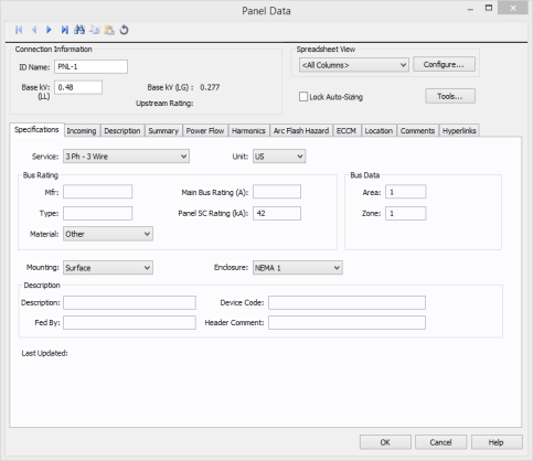
Figure 1: Panel Data Dialog Box
ID Name: Uniquely identifies the panel. This ID name is sometimes referred to as the panel name, and can be up to 16 characters long. The names default to PNL-1, PNL-2, PNL-3, and so on as you enter new panels on the one-line diagram, but you can change those names later if needed.
Base kV: The base kV of the panel.
Upstream Rating: The minimum amp rating of equipment that is upstream from the panel (such as breakers, transformers, or cables). This information is for reference in certain specific configurations of EasyPower and is not generally visible.
Spreadsheet View and Configure: See Spreadsheet View for information about these options.
Lock Auto-Sizing: When this check box is selected, the panel cannot be auto-sized.
Use Spreadsheet View to configure the columns that appear in the spreadsheet. You can create new configurations that display only selected columns. To create a new configuration, click Configure. In the Database Print Config dialog box, type the new configuration name in the Configuration field, and select the desired column headings in the Columns pane.
Use the Select All check box to include all the columns, or Clear All to clear all columns and select only those you want to see.
Use Delete to remove the selected configuration.
Close saves your changes and closes the dialog box.
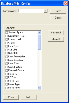
Figure 2: Database Print Config Dialog Box
If you have multiple configurations saved, you can display the desired configuration by selecting it in the dialog box.
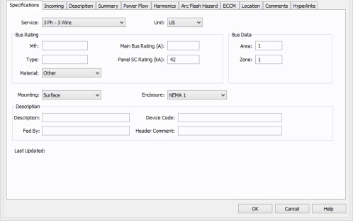
Figure 3: Specifications tab of Panel Data Dialog Box
Service: The service for the panel. Select from 3 Phase - 3 Wire, 3 Phase - 4 Wire, 1 Phase - 2 Wire, or 1 Phase - 3 Wire.
Unit: Choose either U.S., Metric, or CSA.
These are all user-defined fields.
Mfr: Use this text field to describe the panel manufacturer.
Type: Use this text field to further describe the panel manufacturer model.
Material: Select the material for the panel, from aluminum, copper, or other.
Main Bus Rating (A): The current rating of the main bus.
Panel SC Rating (kA): The rating of the bus used in calculating the short circuit duties for SmartDuty™.
Area: Area numbers are used to uniquely define different areas of the electrical system. These areas can then be used for creating specific text reports from analysis operations that represent subsets of the system. For example, typical paper plant areas may be the power house (Area 1), caustic plant (Area 2), pulp mill (Area 3), and paper machine (Area 4). Area numbers are positive integers between 1 and 999.
Zone: A zone number is a sub-area. This allows even more specific reporting. You might want to define the pulp mill as Area 3 and the digester electrical equipment as Zone 2. Specific reports can then be generated for this combination without including the entire pulp mill or the other digesters.
Mounting: The mounting for the panel. Select from flush, surface, or free standing.
Enclosure: The enclosure for the panel. Select from NEMA 1, NEMA 3R, NEMA 4, NEMA 7, NEMA 9, or NEMA 12.
Description: Use this field to describe the panel.
Device Code: You can type letters or numbers to describe the device code for the panel. The information can be converted and printed as a QR code on arc flash labels.
Fed By: Use this field to indicate the transformer or the power supply source feeding the panel.
Header Comment: Use this field for any comment on the panel.
Last Updated: The date and time the panel data was last updated is displayed here.
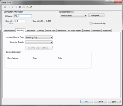
Figure 4: Incoming Tab in Panel Data
Incoming Device Type: You can select the type of incoming protective device type for the panel. The choices available are:
Incoming Branch: You can select the incoming branch equipment such as cables, transformers or busways. All the branches connected to the panel in the one-line are displayed in the list.
Incoming Device Settings: Opens the data dialog for the main fuse or main breaker that has been specified as the incoming device type. Refer to Low Voltage Breaker Data or Fused Switch Data for details.
Device Information: Information on the selected main breaker or main fuse.
This is a spreadsheet listing similar to the Device Library. When you place a new panel on the one-line, the first time you open its database dialog and click on the Description tab, EasyPower displays the Panel Schedule Spreadsheet Creation Wizard which enables you to select the number of rows you want. Clear the check box at the bottom of the wizard dialog if you don't want it to appear with each new panel.
When you click on the Description tab, additional buttons become available on the panel dialog box toolbar. Some of these buttons are the same as those in the Device Library (see EasyPower Device Library) and they offer another way to add rows if the wizard is not used.
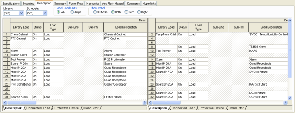
Figure 5: Description Tab of Panel Data Dialog Box
Library: The list contains all of the same schedules as the Device Library. To enter a listing other than those contained in the list, create a new page in the panel section of the Device Library.
Schedule: This list enables you to specify in which Device Library Schedule your chosen Library Load spreadsheet is located. To enter a listing other than those contained in the list, create a new page in the panel section of the Device Library.
Panel Load Units: Select the panel load units, from VA or Amps.
View: These options enable you to choose which of the panels you want to view: Left, Right or Both. The choice 3 Phase shows the ABC buses in the middle with the loads on both sides of the spreadsheet.
Export: The spreadsheets can be exported to metafiles (.WMF) and delimited database text files (.CSV).  Export is beside the Print button on the panel dialog box toolbar when the viewing the Description tab.
ECR Type: This is a reference for a type of electrical change request. It is only used in very specific configurations of EasyPower and is otherwise hidden.
Preassigned: Indicates if a change request is pending for this item. It is only used in very specific configurations of EasyPower and is otherwise hidden.
Library Load: This list corresponds directly to the Library Load column in the Device Library. After you have made selections in the Library, Schedule and Library Load fields, all of the following data cells are automatically filled in as soon as you click on another cell. You may also double-click on the cell to enter something different than what is listed.
Status: The column is a toggle "On/Off" to indicate if this particular item is currently connected to the panel. Turning any load as “off” is similar to deactivating them in the one-line.
Load Type: You can select from three types of load:
You can specify the Facility, Location and Floor of the panel row. Facilities, locations, and floors are set up on the menu beneath Tools > Options.
The rest of the fields correspond directly to those in the Device Library. See EasyPower Device Library for more information.
Panels are validated upon creation. That means that if you create a panel and do not input any data, you can still go into an analysis focus without receiving an error message. When you create a row in this spreadsheet the loads are set to zero until you change them. This means the panel (unlike the MCC) remains validated for analysis even after you have created rows but have not input any data.
If you are making a custom entry, you will notice that many of the data cells contain lists of items. Some of the cells have bold headings, and when they are selected the Calculate button becomes active. Clicking it calculates the data for those cells. You can select several cells at a time before clicking the Calculate button. For instance, clicking on the header selects the entire column.
Because the panel is a library, along with the Calculate button, all of the other editing features are identical to those listed in the customizing section for the Device Library. See Customizing the Library for more information.
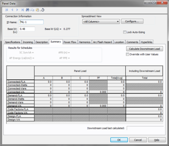
Figure 6: Summary tab of Panel Data Dialog Box
The summary tab sums all the connected loads and displays results for total connected, demand, code factor and design. There are two sections in this summary: Panel Load and Including Downstream Load.
This summarizes the loads fed directly from this panel. It does not include loads fed through downstream sub-panels. These are not user-definable fields. They are updated automatically when you make changes in the spreadsheet of the Description tab. The watts and vars shown in this table do not reflect the downstream load of the sub-panels.
| Connected W | A phase) | Total of the |

|
of (VAA * PF) |
| Connected VAR | (A phase) | Total of the |
|
of (VA2A - W2A)1/2 |
| Connected W | (B phase) | Total of the |
|
of (VAB * PF) |
| Connected VAR | (B phase) | Total of the |
|
of (VA2B - W2B)1/2 |
| Connected W | (C phase) | Total of the |
|
of (VAC * PF) |
| Connected VAR | (B phase) | Total of the |
|
of (VA2C - W2C)1/2 |
| Demand W | (A phase) | Total of the |
|
of (VAA * PF) * DF |
| Demand VAR | (A phase) | Total of the |
|
of (VA2A - W2A)1/2 * DF |
| Demand W | (B phase) | Total of the |
|
of (VAB * PF) * DF |
| Demand VAR | (B phase) | Total of the |
|
of (VA2B - W2B)1/2 * DF |
| Demand W | (C phase) | Total of the |
|
of (VAC * PF) * DF |
| Demand VAR | (B phase) | Total of the |
|
of (VA2C - W2C)1/2 * DF |
Loads connected through downstream sub-panels and buses are summarized in this section.
Override with User Values: This check box enables you to enter your own data. You can enter measured data or assumed data in the available fields. If this check box is not enabled then the program calculates all the downstream loads and displays the total. For this feature to work, it is necessary to have a source upstream to the panel. This feature is applicable only to radial distribution systems. Downstream branches with any power source are not accounted for.
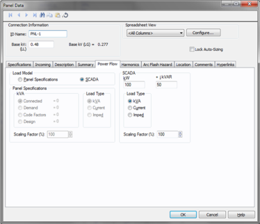
Figure 7: Power Flow Tab of Panel Data Dialog Box
Load Model: Enables you to select the panel kVA from the Specified data or from SCADA (Supervisory Control and Data Acquisition) data. SCADA data can be read in by clicking the  EasyPower button and then clicking Import (toolbar menu: File > Import).
kVA: Select the method used to determine the kilovolt-ampere for power flow analysis. Choose between:
Load Type: Panels can be modeled for the power flow solution in several different ways.
Scaling factor: Provides an easy way of adjusting the total panel load used in determining power flows.
SCADA data is derived from real time, or metered data, and converted to an ASCII format which can be read into EasyPower. SCADA data is read in as a 100% scaling factor load. The load value is multiplied by the user-defined scaling factor. This provides a way to adjust SCADA loads to form new cases.
kW: The kW value as read in from the SCADA ASCII file.
kVAR: The kVAR value as read in from the SCADA ASCII file.
Load Type: SCADA data can be modeled in the power flow solution in several different ways. SCADA load type is set in the ASCII file, and can be changed by you.
Constant Current: This model alone is generally not used for power flow simulation.
Constant Impedance: This model is for loads such as incandescent lighting, ranges, and resistance space heaters.
Scaling factor: Provides an easy way of adjusting the total SCADA load used in determining power flows. By changing the scaling factor, the actual kW +j kVAR read in from the ASCII file remains static; however the load used in the power flow is adjusted by this factor.
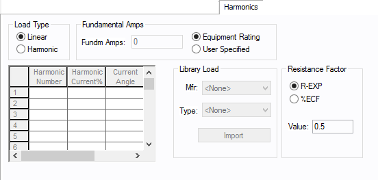
Use the Harmonics tab to indicate whether this equipment item is introducing harmonics into your power system.
The default is Linear, indicating the equipment does not produce harmonics. Choosing Harmonic makes the item an harmonic source and makes other fields in this tab available to edit.
Note:
For an adjustable frequency drive (AFD), the Load Type is always Harmonic.
For motors, the Load Type is Harmonic if the With Adjustable Frequency Drive (AFD) check box is selected on the Specifications tab of the motor; otherwise, it is always Linear.
Use the spreadsheet to enter the harmonic spectrum produced by this item. You can enter up to 30 different harmonics in each equipment item. In the spreadsheet, enter the Harmonic Number (such as 5 for the 5th harmonic), the Harmonic Current in percent of the Fundamental Amps, and the Current Angle. By indicating the current angle, you can simulate transformer phase shift effects on rectifiers so appropriate canceling can take place. The harmonic may be integer or non-integer.
Common harmonic spectra may be entered from the device library. For instructions on how to enter your own spectra information, see Harmonics with Spectrum™. After selecting a particular device library spectrum from the Mfr and Type lists, click Import, and that spectrum is entered into the harmonic spreadsheet.
EasyPower offers two methods for calculating RH:
RH = RFund * H R-EXP
RH = RFund * (1+ECF*H2)/(1+ECF)
EasyPower defaults all skin effect correction to R-EXP and a value of 0.5.
| R-EXP | %ECF | |
|---|---|---|
|
Transformer |
0.5-1.0 |
1.0-3.0 |
|
Utility |
0.0-0.8 |
- |
|
Generator |
0.3-0.6 |
- |
|
Line/Cable |
0.5 |
- |
|
Reactor |
0.5-1.0 |
0.8-3.0 |
|
Motor |
0.2-0.4 |
- |
Use to set the fundamental amps. The options are as follows:
To use fundamental current calculated by power flow, select Calculated from Power Flow in the Summation Fundamental Voltage area of the Harmonics Options > Control dialog box.
The arc flash hazard tab is similar to that of an MCC. See Arc Flash Hazard for details. Since the panel can be faulted like a bus, you can perform arc flash hazard analysis directly.
Note: This information is used in certain specific configurations of EasyPower and is not generally visible.
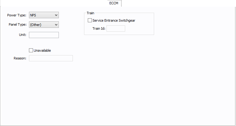
Figure 8: ECCM Tab
Power Type: The power type for the panel. Select from NPS (normal power supply), EPS (emergency power supply), or CPS (critical power supply).
Panel Type: The panel type for the panel. Select from (Other), Tool, Facility, or Tool/Facility. For the panel to be used as a tool point of connection, the type must be Tool or Tool/Facility.
Unit: Use to describe the unit for the panel data (up to 16 characters). You can enter both numbers and letters.
Unavailable: Select to note that this panel is unavailable. You can specify a reason why in the Reason box.
Reason: Use to describe why the panel is unavailable (up to 32 characters). You can enter both numbers and letters.
Service Entrance Switchgear: Select the option to create a train. A train is a redundant power subsystem.
Train ID: The ID for the train. Buses and equipment that are downstream of the service entrance switchgear inherit the train ID from the upstream switchgear.
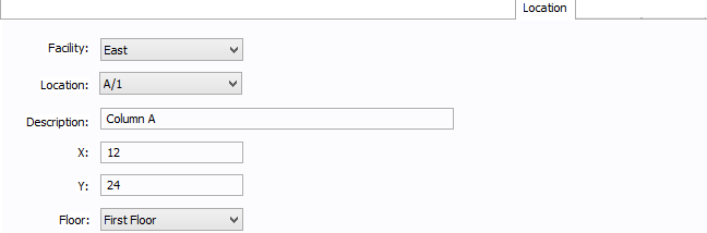
Figure 9: Location Tab
You can specify the location of the equipment on the floor of a building. You can give the location a name, specify the X and Y coordinates of the location, and select a floor.
The coordinates could be measured in feet, for example, or they could represent points on a grid. There are no units associated with the coordinates, so you can use whatever measurement makes sense for you.
Facility: The building in which the equipment is located. Facilities are set up under the Tools > Options arrow under Facilities.
Location: The location of the equipment. This is the combination of the Ref 1 and Ref 2 boxes set up on the location. Locations are set up under the Tools > Options arrow under Locations.
Description: This is a description of the location. The default description comes from the location, but you can change it. You can type up to 32 characters.
X: This is a numeric value (such as feet or grid locations) that represents the horizontal location. The default X value comes from the location, but you can change it.
Y: This is a numeric value (such as feet or grid locations) that represents the vertical location. The default Y value comes from the location, but you can change it.
Floor: Select the floor where the equipment is located. Floors are set up under the Tools > Options arrow under Floors.
For more information, see Facilities, Floors, and Locations.
This tab is read-only and appears only if you have imported data from an SKM Data Format file. See Importing an SKM Format File for more information.
See Comments for information.
See Hyperlinks for information.
| Database Technical Reference |