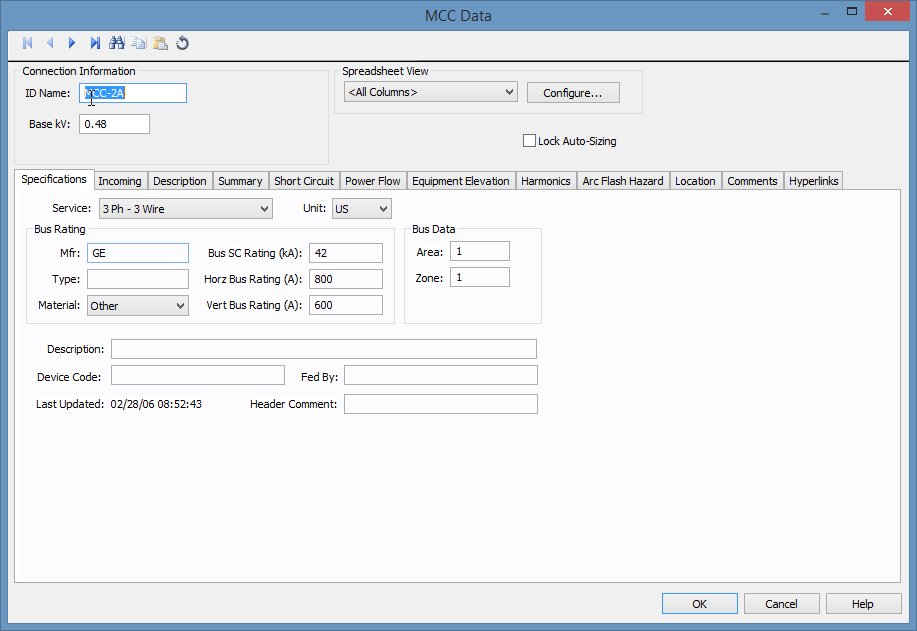
Figure 1: MCC Data Dialog Box
This dialog box includes the following areas and tabs:
Figure 1: MCC Data Dialog Box
| Option | Description |
|---|---|
| ID Name |
Uniquely identifies the MCC. This ID name can be up to 16 characters long. The names default to MCC-1, MCC-2, MCC-3... as you enter new MCCs on the one-line, but you can change those names to something more descriptive if needed. |
| Base kV | The base kV of the MCC. MCC’s are modeled like a bus in many ways. You can connect cables, busways or transformers to it, and perform fault calculations. |
| Spreadsheet View and Configure | See Spreadsheet View for information about these options. |
| Lock Auto-Sizing | When this check box is selected, the MCC cannot be auto-sized. |
These are the specifications for the MCC including the bus.
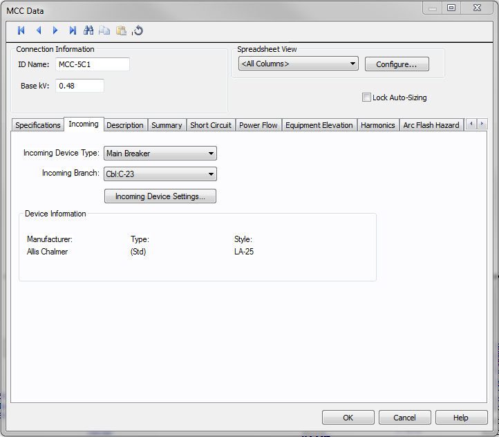
Figure 2: Incoming Tab
| Option | Description |
|---|---|
| Incoming Device Type |
You can select the type of incoming protective device type for the MCC. The choices available are:
|
| Incoming Branch | Select the incoming branch equipment such as cables, transformers or busways. All the branches connected to the MCC in the one-line are displayed. |
| Incoming Device Settings | Opens the data dialog for the main fuse or main breaker specified as the incoming device type. See Low Voltage Breaker Data or Fused Switch Data for more information. |
This is a spreadsheet listing similar to the Device Library. When you place a new MCC on the one-line, the first time you open its database dialog and click on the Description tab, EasyPower displays the MCC Spreadsheet Creation Wizard which enables you to select the number of rows you want. Clear the check box at the bottom of the Wizard dialog if you don't want it to appear with each new MCC. You can insert or append new rows in the spreadsheet if you need them later.
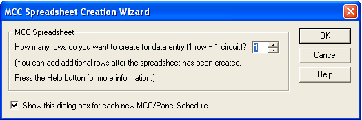
Figure 3: MCC Spreadsheet Creation Wizard Dialog Box
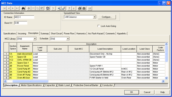
Figure 4: Description Tab of MCC Data Dialog Box
Note: When you click on the Description tab, additional buttons become available on the MCC Data dialog box toolbar. Some of these buttons are the same as those in the Device Library (see EasyPower Device Library) and they offer another way to add rows if the Wizard is not used.
| Option | Description |
|---|---|
| MCC Library |
The list contains all of the same schedules as the Device Library. To enter a listing other than those contained in the list, create a new page in the MCC section of the Device Library. See EasyPower Device Library for more information. |
| Schedule | This list enables you to specify which Device Library Schedule your chosen Library Load spreadsheet is located in. To enter a listing other than those contained in the list, create a new page in the MCC section of the Device Library. See EasyPower Device Library for more information. |
| Export | The spreadsheets can be exported to metafiles (.WMF) or delimited database text files (.CSV). Export is beside the Print button on the MCC/Panel dialog box toolbar when the viewing the Description tab. |
Note: The Section Space and Equipment Name are not necessary for calculation purposes but are used to match the way they are organized in the MCC.
| Option | Description |
|---|---|
| Section Space | Enter the location of the individual bucket in the MCC. Typical entries would be 1A, 1B, 2A, 2B, 2C, and so on. |
| Equipment Name | Enables you to identify each piece of equipment. |
| Library Load | This list corresponds directly to the Library Load column in the Device Library. After you have made selections in the MCC Library, Schedule and Library Load fields, all of the data cells that follow are automatically filled in when you click on another cell. You can also double-click on the cell to enter something different than what is listed. |
| Status | The third column is a toggle "On/Off" to indicate if this particular item is currently connected to the MCC schedule. This affects the power flow and short circuit current contribution. |
| Load Type |
You can select different kinds of loads such as motors, loads, or sub-MCC/panel. Based on the load type selected, various analysis are possible. When you select a load type, the cells in the row that do not apply become unavailable. You might see a Data button indicating you need to enter data specific to the load type. Cells highlighted in red require data in order to perform any analysis. The following load types are available:
|
The rest of the fields correspond directly to those in the Device Library. MCCs are validated upon creation. That means that if you create an MCC and do not input any data, you can still go into an analysis focus without receiving an error message. However, after you create a row in this spreadsheet, you will not be able to enter an analysis focus until all required data is input. The cells which require data for analysis are highlighted in red.
If you are making a custom entry, you will notice that many of the data cells contain lists of items. Some of the cells have bold headings, and when they are selected the Calculate button becomes active. Clicking it calculates the data for those cells. You can select several cells at a time before clicking Calculate. For instance, clicking on the header itself selects the entire column.
Because the MCC is a library, along with the Calculate button, all of the other editing features are identical to those listed in the customizing section for the Device Library. See Customizing the Device Library for more information.
Use Spreadsheet View to configure the columns that appear in the spreadsheet. You can create new configurations that display only selected columns. To create a new configuration, click Configure. In the Database Print Config dialog box, type the new configuration name in the Configuration field, and select the desired column headings in the Columns pane.
Use the Select All check box to include all the columns, or Clear All to clear all columns and select only those you want to see.
Use Delete to remove the selected configuration.
Close saves your changes and closes the dialog box.
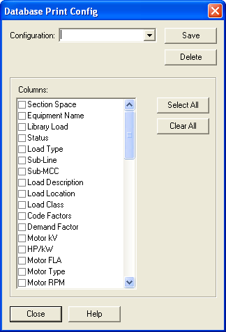
Figure 5: Database Print Config Dialog Box
If you have multiple configurations saved, you can display the desired configuration by selecting it in the dialog box.
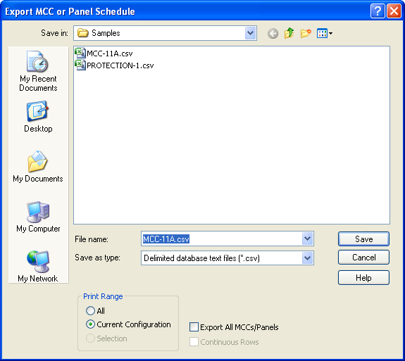
Figure 6: Export dialog for MCC or Panel Schedule
| Option | Description |
|---|---|
| Save as type | You can save the schedule as a CSV (spreadsheet) file or as a WMF (picture) file. |
| Print Range |
Choose one of the following.
|
| Export All MCCs/Panels | When clear, only this MCC or panel is exported. When selected, all the MCC and Panels are exported. |
The Summary tab of MCC Data dialog box provides the total load on the MCC and the load that must be used in designing.
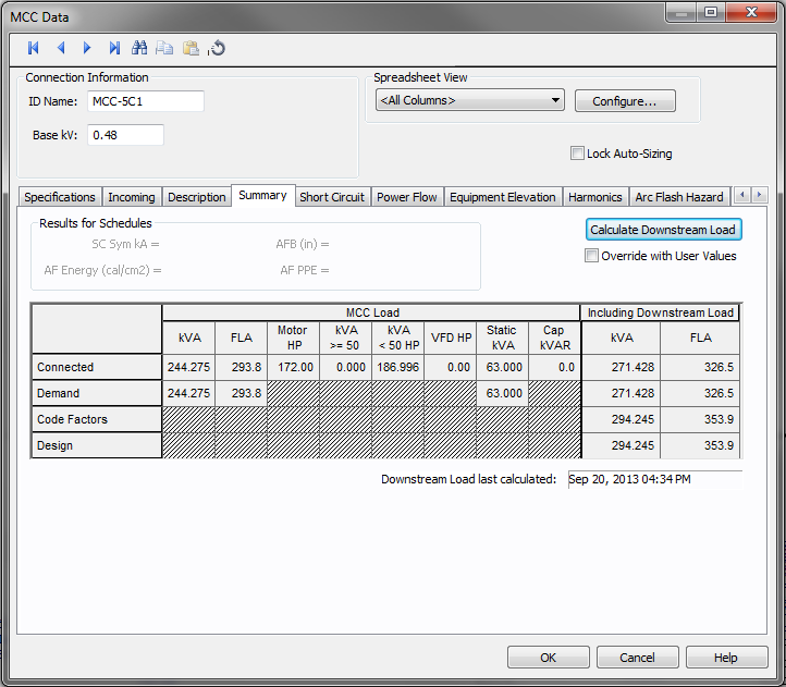
Figure 7: Summary tab of MCC Data Dialog Box
| Option | Description |
|---|---|
| Calculate Downstream Load | Calculates the total load on the MCC, taking into account the connected load, demand factors, diversity factors and NEC code factors. |
| Override with User Values | This check box enables you to enter data in the Total Downstream Load – kVA column. |
The spreadsheet has two sections – MCC Load and Including Downstream Load.
| Option | Description |
|---|---|
|
MCC Load This spreadsheet section provides the summary of the loads fed by the feeders of the MCC. The loads from the sub-MCC and sub-panels are not included in this section. |
|
| Total kVA | This is the aggregate load. |
| Total FLA | Total load in amps. |
| Motor HP | The total HP for the items with "On" in the Status column of the Description section. |
| Motor kVA >= 50 HP | The total KVA for connected items equal to or greater than 50HP. |
| Motor kVA < 50 HP | The total KVA for connected items less than 50HP. |
| Static kVA | Total kVA of the loads. |
| Capacitor kVAR | Total kVARs of all the capacitors |
| (Calculations) | |
| Connected | Connected kVA = [(SkW)2 + (SkVAR)2]1/2 |
| Demand |
Demand kVA = [S(kW * DF)2 + S(kVAR * DF)2] ½ Where DF is the individual demand factor of each MCC circuit. |
| Code Factors |
Code Factors kVA = [(kWL + SkW)2 + (kVARL + SkVAR)2]1/2 Where, kWL = Code Mult Factor * kW for largest motor in MCC. KVARL = Code Mult Factor * kVAR for largest motor in MCC. kW and kVAR are for the rest of the loads. The code multiplying factor is specified in Tools > Options > Equipment. |
| Design |
Design kVA = Code Factors kVA * Diversity Factor * Design Factor Diversity Factor is specified in the Specifications tab of MCC Data. The Design Factor is specified in Tools > Options > Equipment. |
|
Including Downstream Load This provides the sum of the loads fed by feeders inside the MCC and the sub-MCC and sub-panels. |
|
| kVA | Total kVA load calculated. You can enter your own values in these fields by selecting the check box for Override with User Values. |
| FLA | Total FLA load calculated. You can enter your own values in these fields by selecting the check box for Override with User Values. |
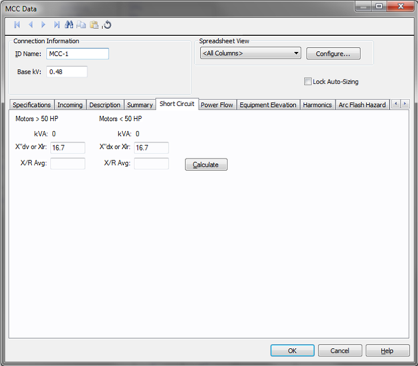
Figure 8: Short Circuit Tab of MCC Data Dialog Box
| Option | Description |
|---|---|
| kVA >50Hp | Total kVA of the motors which are greater than 50Hp. |
| X"dv or Xlr | Is set at the default value for >50Hp. You can enter your own value and it applies to all the motors greater than 50Hp. |
| X/R Avg | Calculate fills this field using values from the spreadsheet. You can enter your own X/R average. |
| KVA <50Hp | Total kVA of the motors which are less than 50Hp. |
| X"dx or Xlr | Is set at the default value for <50Hp but you can change this. You can enter your own value and it applies to all the motors less than 50Hp. |
| X/R Avg | Calculate fills this field using values from the spreadsheet. You may enter your own X/R average. |
| Calculate | Click to calculate the X/R averages for motors greater than and less than 50 HP. |
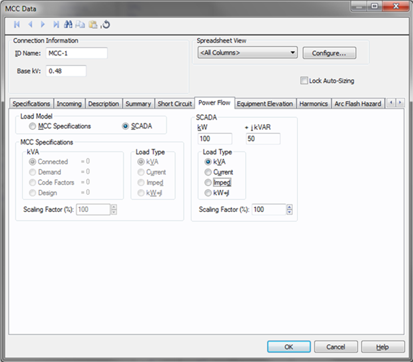
Figure 9: Power Flow Tab of MCC Data Dialog Box
See MCC Elevation for information about this tab.
Use the Harmonics tab to indicate whether this equipment item is introducing harmonics into your power system.
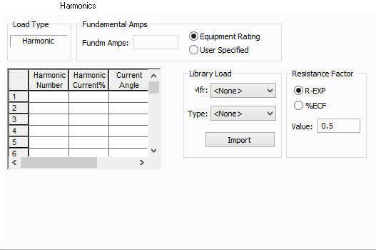
Figure 10: Harmonics Tab
| Option | Description | |||||||||||||||||||||
|---|---|---|---|---|---|---|---|---|---|---|---|---|---|---|---|---|---|---|---|---|---|---|
| Load Type |
The default is Linear, indicating the equipment does not produce harmonics. Choosing Harmonic makes the item an harmonic source and makes other fields in this tab available to edit. Note:
|
|||||||||||||||||||||
| Fundamental Amps |
Use to set the fundamental amps. The options are as follows:
To use fundamental current calculated by power flow, select Calculated from Power Flow in the Summation Fundamental Voltage area of the Harmonics Options > Control dialog box. |
|||||||||||||||||||||
| Harmonic Spreadsheet |
Use the spreadsheet to enter the harmonic spectrum produced by this item. You can enter up to 30 different harmonics in each equipment item. In the spreadsheet, enter the Harmonic Number (such as 5 for the 5th harmonic), the Harmonic Current in percent of the Fundamental Amps, and the Current Angle. By indicating the current angle, you can simulate transformer phase shift effects on rectifiers so appropriate canceling can take place. The harmonic may be integer or non-integer. |
|||||||||||||||||||||
| Library Load |
Common harmonic spectra may be entered from the device library. For instructions on how to enter your own spectra information, see Harmonics with Spectrum™. After selecting a particular device library spectrum from the Mfr and Type lists, click Import, and that spectrum is entered into the harmonic spreadsheet. |
|||||||||||||||||||||
| Resistance Factor |
EasyPower offers two methods for calculating RH:
RH = RFund * H R-EXP RH = RFund * (1+ECF*H2)/(1+ECF) EasyPower defaults all skin effect correction to R-EXP and a value of 0.5.
|
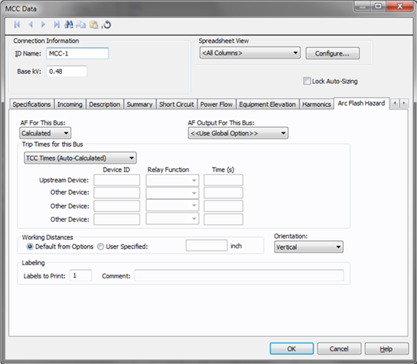
Figure 11: Arc Flash Hazard tab of MCC Data
Since the MCC can be analyzed like a bus, you can also obtain arc flash hazard assessment results for MCC. The arc flash tab is similar to that of bus data. However, the equipment type is forced to MCC/Panel, since an MCC cannot be another type. You can specify the trip time as available in the default library, enter the incident energy or you can enter the trip times in the fields. For detailed descriptions see Arc Flash Hazard.
See Location for more information.
This tab is read-only and appears only if you have imported data from an SKM Data Format file. See Importing an SKM Format File for more information.
See Comments for information.
See Hyperlinks for information.
| Database Technical Reference |
|
|