|
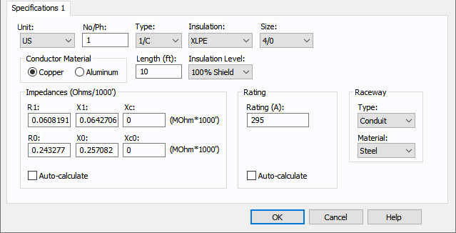
Unit
|
Choose either U.S., CSA, Metric or Per Unit. If you choose Per Unit, all fields except those in the Impedance (PU) section become unavailable.
|
|
No/Phase
|
Total number of cables modeled for the same circuit. This is also referred to in the industry as “sets of cables” or “number of runs.” The default of one (1) means one conductor per phase. Two (2) means two conductors in parallel per phase, and so on. When two or more conductors are in parallel, the impedance of the circuit is decreased by that factor. The impedances shown in the dialog box are for one conductor only, and are not based on the No./Phase field, so if you enter these values instead of using Auto-calculate, make sure they are for one conductor only. This lets you easily check handbook values without additional arithmetic. The per-unit impedances listed in a database report considers the total number of conductors.
|
|
Type
|
Five different cable types can be modeled. Cable type is used in determining the impedance of the conductor.
- 1/C - One conductor. Three separate conductors are used for a circuit, one each for A phase, B phase and C phase.
- 3/C - Three conductor. This is the same as three separate conductors, except that the conductors are encased with an insulated overall outer jacket effectively forming one cable. The cable may or may not have an interstitial ground wire.
- IAA - Interlocked armor aluminum. This is the same as the three conductor cable except that the outer jacket is made of aluminum instead of protective insulation. IAA is a generic term for describing any type of aluminum jacket including continuous sheath products such as Okonite CLX.
- IAS - Interlocked armor steel. This is the same as IAA except that the outer jacket is made of steel instead of aluminum.
- MAC - Messenger aerial cable. Messenger aerial cable is three separate conductors bundled together with a messenger cable easy hanging from poles. Because the conductors are held in a triangular fashion with the bundling, the impedance of this configuration is the same as for the 3/C cable.
Note: For Teck cables, select the CSA unit. For single conductor Teck, select 1/C and for 3-conductor Teck, select IAA for aluminum armor or IAS for steel armor. Look for Teck or Teck-90 in the Insulation type.
|
|
Insulation
|
US Low Voltage Insulation (1000 volts or less):
- EPR - Ethylene Propylene Rubber.
- PVC - Polyvinyl chloride.
- RH - Heat Resistant Rubber, 75oC.
- RHH - Heat Resistant Rubber.
- RHW - Moisture and Heat Resistant Rubber. This is the 480 volt equivalent of EPR.
- THHN - Heat Resistant Thermoplastic.
- THWN - Moisture and Heat Resistant Thermoplastic.
- THW - Moisture and Heat Resistant Thermoplastic.
- TW - Thermoplastic insulated moisture resistant cable.
- XHHW - Moisture and Heat Resistant Crosslinked Synthetic Polymer. This is the 480 volt equivalent of XLPE.
US High Voltage Insulation (Over 1000 volts):
- XLPE - Crosslinked Polyethylene.
- XLPE-133% - Crosslinked Polyethylene with 133% insulation.
- XLPE-NJ - Non-Jacketed Crosslinked Polyethylene.
- XLPE-NJ-133% - Non-Jacketed Crosslinked Polyethylene with 133% insulation.
- XLPES - Shielded Crosslinked Polyethylene.
- XLPES-133% - Shielded Crosslinked Polyethylene with 133% insulation.
- EPR - Ethylene Propylene Rubber.
- EPR-133% - Ethylene Propylene Rubber with 133% insulation.
- EPR-NJ - Non-Jacketed Ethylene Propylene Rubber.
- EPR-NJ-133% - Non-Jacketed Ethylene Propylene Rubber with 133% insulation.
- EPRS - Shielded Ethylene Propylene Rubber.
- EPRS-133% - Shielded Ethylene Propylene Rubber.
- PILC - Paper Insulated Lead Sheath.
- PILC-133% - Paper Insulated Lead Sheath with 133% insulation.
Note: For line-to-neutral single-phase cables, the program looks up the library information for insulation based on the equivalent 3-phase voltage.
|
|
Insulation level
|
Denotes whether the selected insulation type has extra thickness for a higher level of insulation.
Examples include 100% or 133% for the selected insulation type.
|
|
Size
|
Conductor size in AWG, MCM, or mm2. Cable size is used in determining the impedance of the conductor.
|
|
Conductor Material
|
The conductor material (copper or aluminum).
|
|
Length
|
Length of the cable in feet or meters.
|
| Impedances |
| |
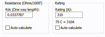
Impedances are described as Ohms/1000 feet, Ohms/KM or PU. Zero sequence impedances are described as the positive sequence impedance using a Z0/Z1 multiplier by Kaufmann1, specifically, on page 7.
|
|
R1
|
Positive sequence resistance.
The resistance values are used in power flow, ANSI short circuit, harmonics, dynamic stability and auto design analysis.
For IEC 60909 short circuit, separate resistance values are used. Maximum short circuit currents use resistance at 20°C. Minimum short circuit currents use the resistance at the final conductor temperature at the end of the short circuit. EasyPower calculates these resistances based on the resistances R1 and R0 and the Field Temperature of Conductor from the Specifications 2 tab. If you enter the R1 and R0 values manually, be sure to set the Field Temperature of Conductor to get the appropriate resistances for IEC short circuit. The Database Browser shows the per-unit resistances for maximum and minimum short circuit currents.
Note: For single phase this is the effective resistance of the phase or live conductor. When the neutral conductor is the same as the phase conductor or when the neutral conductor data is not available, analysis doubles the value of the phase conductor to account for the return path. For an unequal neutral conductor size, the program uses the resistance from the Neutral tab of the Cable Data dialog box to obtain the total resistance.
|
|
X1
|
Positive sequence reactance.
Note: For single phase this is the effective resistance of the phase or live conductor. When the neutral conductor is the same as the phase conductor or when the neutral conductor data is not available, analysis doubles the value of the phase conductor to account for the return path. For an unequal neutral conductor size, the program uses the resistance from the Neutral tab of the Cable Data dialog box to obtain the total resistance.
|
|
Xc
|
Positive sequence capacitive reactance. The unit is Mohm*1000ft or Mohm*1000meters.
Note: Capacitive reactance is ignored in analysis if you enter a zero here.
|
|
R0
|
Zero sequence resistance. If you enter this value as zero (0.0), the positive sequence impedance is used.
The resistance values are used in power flow, ANSI short circuit, harmonics, dynamic stability and auto design analysis.
For IEC 60909 short circuit, separate resistance values are used. Maximum short circuit currents use resistance at 20°C. Minimum short circuit currents use the resistance at the final conductor temperature at the end of the short circuit. EasyPower calculates these resistances based on the resistances R1 and R0 and the Field Temperature of Conductor from the Specifications 2 tab. If you enter the R1 and R0 values manually, be sure to set the Field Temperature of Conductor to get the appropriate resistances for IEC short circuit. The Database Browser shows the per-unit resistances for maximum and minimum short circuit currents.
|
|
X0
|
Zero sequence reactance. If you enter this value as zero (0.0), the positive sequence impedance is used.
|
|
Xc0
|
Zero sequence capacitive reactance.
Note: Capacitive reactance is ignored in analysis if you enter a zero here.
|
|
Rating
|
Conductor rating in amperes. When the Auto-calculate checkbox is selected, this value is retrieved from the device library and is for one conductor. You need to input the proper rating. The 75(C) rating is shown, to indicate lug ratings, below the rating field if auto-calculate is used to determine the rating (low voltage only). You can derate cable amp rating based on ambient temperature and the number of conductors in conduits or raceways by specifying the Ambient Temp and the Duct Config field in the Specification 2 tab of the dialog box. For the Ambient Temp derating to take effect, you need to specify the derating standard in Tools > Options > Equipment.
|
|
Auto-calculate
|
Fills in computed values for the R1, X1, R0, X0, Xc, and Xc0 fields. There is a separate checkbox for the Rating (A) field. The calculations are based on the cable specifications and the type of ground circuit.1,2
If the checkbox is cleared, you can enter your own calculated values.
Reference:
1 General Electric Wire and Cable Handbook, March 31, 1983.
2 IEC 60228 Conductors of Insulated Cables, Third Edition 2004-11
Note: This checkbox is not available if the unit on the Specifications 1 tab is selected as Per Unit.
|
| Raceway Configuration |
|
Type
|
Medium in which the conductor is supported or run (conduit, cable tray, air, or direct buried). If none is selected, the cable ampacity defaults to 10A.
Note: For buried conduits, you can apply the derating for ampacity in the Duct Config field on the Specifications 2 tab.
|
|
Material
|
Raceway material, which can be either metallic such as steel, or non-metallic such as aluminum, PVC, IMT, or EMT. This value is used in determining reactances.
|