Cable - Specifications 2 Tab
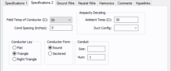
Figure 1: Specifications 2 Tab (AC Cable Shown)
Note: All fields have a substantial effect on conductor impedances when using the Calculate button.
| Description | Option |
|---|---|
|
Field Temp of Conductor (C) |
Temperature of the loaded conductor. This can be varied from 25C to 250C depending on the type of study being performed. Cable temperature is used in determining the resistance of the conductor. The resistance increases with the conductor temperature. Note: This is not the ambient air temperature or the ground temperature. |
|
Cond Spacing |
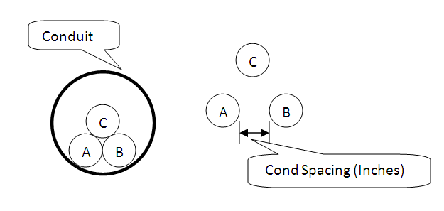
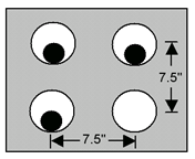
Distance between the outside insulation or jacket edges of adjacent phase conductors. This will affect the reactance calculations. All three spacings are modeled as the same or as a GMD equivalent. Note: This is not the center to center distance. See figure below.
Figure 2: Conductor Spacing: Zero Spacing (Left) and With Spacing (Right) |
|
Ampacity Derating |
|
|
Duct Config |
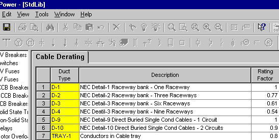
This field allows for cable ampacity derating based on the number of conductors in the conduit, tray or duct. Select from D-1, D-2, and so on, which correspond to NEC Detail 1, NEC Detail 2, and so on, of the National Electric Code. If this field is left blank, a 1.0 multiplier is assumed for the ampacity calculations. The rating factors are stored in the standard device library and can be customized if needed. If you need to derate cables based on number of conductors in the conduit or tray, you can add to the library.
Figure 3: Cable Derating in the Standard Device Library
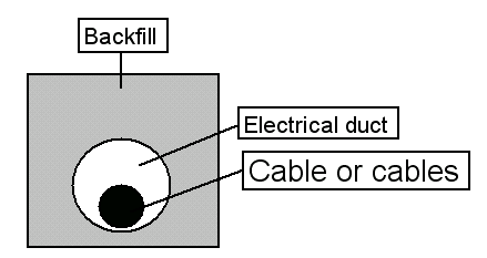
Figure 4: 11.5” X 11.5” Electrical duct bank. One electrical duct
Figure 5: 19” X 19” Electrical duct bank. Three electrical ducts For a complete listing of duct configurations, please see article 310 in the National Electric Code. |
|
Ambient Temp |
Ambient air temperature. This is used for ampacity derating based on the standard selected in Tools > Options > Equipment. You can choose US (based on NEC), CSA (based on CEC) or <None> in the Options. No derating is applied when the option is <None>. |
|
Conductor Lay (AC cable only) |
Lay of the conductor, which affects the impedance. 3/C, IAA, IAS, and MAC configurations are always defined with a triangle configuration and zero spacing even if you choose a different configuration. Single conductor cables, however, can be in flat, triangle or a right triangle configuration with any spacing factor. |
|
Conductor Form |
Conductor form is determined by the extrusion process of the copper or aluminum. Select either round or sectored. |
|
Conduit Size & Num |
Size and number of conduits. This does not affect the impedance or ampacity calculations, but is stored as data. SmartDesign™ populates this field while automatically sizing the cables. The size appears in inches or millimeters depending on how Units are specified on the Specifications 1 tab. |
More Information
- Cable Data
- Database Dialog Box Toolbar
- Cable - Connection Information
- Cable - Specifications 1 Tab
- Cable - Ground Wire Tab
- Cable - Neutral Wire Tab (AC only)
- Cable - Harmonics Tab (AC only)
- Cable - Reliability Tab
- Cable - Comments Tab
- Cable - Hyperlinks Tab
- Cable - Collected Data Tab
- Cable - Media Gallery Tab
- Cable - Appearance Tab