Arcs and Circles
Defining Arcs
When defining arcs for a symbol, such as the arcs in a transformer or shunt, keep in mind the following diagram. The figure below shows a square made up of four quadrants. 0° is shown at the right. The arc movement proceeds clockwise from that point. In the figure, the arc is defined with a start angle of 0° and a sweep angle of 180°.
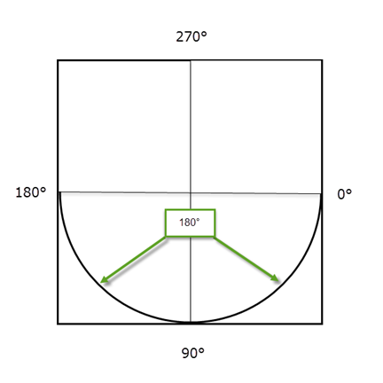
Figure 1: Arc Starting at 0° with a Sweep Angle of 180°
In the figure below, the arc is defined with a start angle of 270° and a sweep angle of 180°.
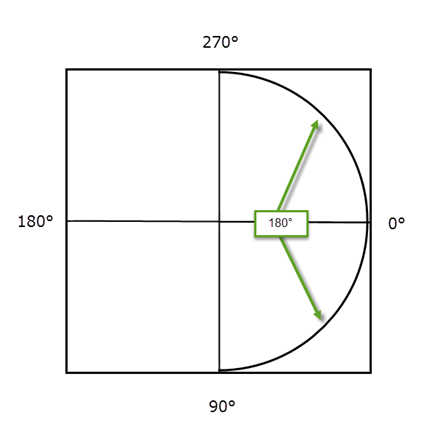
Figure 2: Arc Starting at 270° with a Sweep of 180°
In both of the cases shown above, the sweep angle is 180°, creating a half circle. The difference is in the starting point.
Elliptical Arcs
The examples above demonstrate a circular arc. As the height and width are not specified, they are assumed to be identical, so the result is a circle (although only a portion of the circle is displayed based on the starting point and sweep angle that has been defined).
You can also create an elliptical arc by setting width and height parameters. Use this to flatten the arc. The example below is taken from the symbol template to define a below-bus ANSI capacitor.
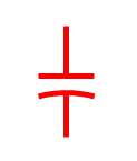
Figure 3: ANSI Capacitor Symbol
<SymbolTemplate>
<Line X1="10" Y1="0" X2="10" Y2="9" />
<Line X1="5" Y1="9" X2="15" Y2="9" />
<Line X1="10" Y1="12" X2="10" Y2="20" />
<Arc Left="2" Top="12" Width="16" Height="6" StartAngle="205" SweepAngle="130" />
</SymbolTemplate>
The first three "Line" values define the straight lines in the symbol. The last set of "Arc" values define the curved line in the symbol. The example below displays the entire elliptical circle that creates the curve, but only the portion between the green dotted lines (defined by the start and sweep angles) are actually displayed in the final symbol. The yellow highlighted area indicates the width (12 grid points) and the height (6 grid points) that determine the overall shape of the ellipse.
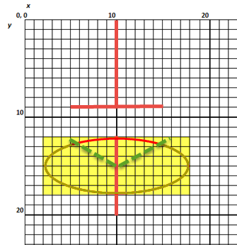
Figure 4: Elliptical Arc Example
Defining Circles
Circles appear similar to arcs but are defined differently. For a circle, you need to define the x and y coordinates, and to specify a radius. All are specified in grid points. For example, in ANSI, for an AC induction motor, the following information is used:
<SymbolTemplate>
<Circle X="8" Y="8" Radius="8" FillStyle="None"/>
<Polyline Points="5 11, 5 5, 8 10, 11 5, 11 11"/>
</SymbolTemplate>
The x and y coordinates determine the center of the circle. The radius originates from the center of the circle. This means that the center of the circle is at coordinates 8,8, and there are 8 grid points on each side of the center to the edge of the circle.
On a grid, that would look like this:
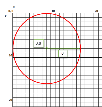
Figure 5: Definition of a Circle for a Motor Symbol
Note: The polyline points are described in a separate topic. See Polylines.
More Information
| Customizing One-line Symbols | Polylines |
| Symbol Definition Tags | Polygons |
| Coordinates | Text |
| Rectangles and Lines | Bezier Curves |
|
|