Symbol Definition Tags
The following table provides more detailed information about some of the XML tagging used to define the symbols. Note the capitalization of the tags—incorrectly capitalized tags are ignored by XML.
Note: The values available for each tag are specified in the EasyPowerSymbols.xsd template file. You can add or modify these values in the template file, but EasyPower will only recognize those values that were defined in the original template. Modifications that were not part of the original template file are ignored by EasyPower.
|
Element Tag |
Definition |
|---|---|
|
<Equipment Type=”XXXX”> |
The type defines the type of equipment –for example, Type = “Utility” means the equipment is a utility. |
|
<GraphicDefinition> |
This defines the graphic characteristics of the symbol. It contains sub-elements that provide information such as the points to which a symbol snaps to grid or connects to other equipment. It also specifies:
|
|
<SnapPoint> |
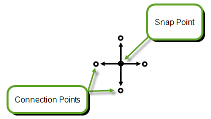
Determines the location at which the item snaps to grid. Measured in pixels, which are based on 96ppi. See additional information under <ConnectionPoint>. For breakers, fuses, and switches, the snap point needs to be centered between the connection point. Tip: In Tools > Options >One-line Symbols, under Display Options, you can select Show snap points to display the snap points on the one-line. |
|
<ConnectionPoint> |
Defines the X and Y coordinates for where the symbol connects to other equipment items on the one-line. For items such as transformers, there can be multiple connection points, with labels such as "From" and "To." For current transformers, you can specify the positive and negative connection points. The positive connection represents a connection at the top of the symbol, while a negative represents a connection at the bottom.
Items such as buses do not have connection points due to the ability to change their size. Connection and Snap Points For best results, ensure your connection points and snap points are aligned so that the equipment is aligned properly on the snap grid.
For breakers, fuses, and switches, the snap point needs to be centered between the connection point. Tip: In Tools > Options >One-line Symbols, under Display Options, you can select Show connection points to display the connection points on the one-line. |
| <ConnectionRectangle> | Defines the connection area for an MCC or panel when they are displayed as a rectangle on the one-line. |
|
<WindingSymbolVisibility> |
Options are Visible or Hidden. This applies only to a transformer and defines whether the winding symbols (delta, wye, or wye ground) of a transformer symbol are visible. |
| <WindingSymbolLocation> | Defines the location of the transformer winding symbols related to a transformer symbol. |
|
<TextTemplate> |
If text appears on the one-line, it is defined here. This controls the location and appearance of the text. You can specify parameters such as:
Note: RelativeX="RightSide" is used to make the X (horizontal) attribute value relative to the right side of the symbol so the text block moves when the symbol is resized. Note: All closed breakers, switches, and fuses must have a location defined for DataText1. See Data Text for Breakers, Switches, and Fuses for more information. |
|
<SymbolTemplate> |
Defines the symbol characteristics. This includes instructions for the shape, size, location, and appearance of the symbol. Shapes include:
Note: A <PadTemplate> is a rectangle that displays below a bus if the Show Pad Symbol check box is selected in the Bus Data dialog box on the Specifications tab. |
 See
See  See
See  See
See  (The top of the utility is made up of rectangles.) See
  See
See More Information
|
|