EasyPower 10.2 Release Details
This topic describes new EasyPower features and enhancements, as well as bug fixes that are included in the release.
For information on the latest service packs for this release, see 10.2 SP1 Release Notes.
Note: New release features often include changes to the database. This may affect what you see in the Database Browser and also what is included when you export data into CSV files. If your existing work processes rely on information from the database, be sure to review your processes after you update your software.
New and Enhanced Feature Details
IEEE 1584-2018 Support
This release includes updates to the program calculations and options to support the new IEEE 1584-2018 standard.
New Standard Calculation Method
In the Short Circuit Options, references to the older IEEE 1584 standard have been renamed to IEEE 1584-2002 and older databases where that standard was selected are now set to use IEEE 1584-2002. When you create a new one-line, the default is now IEEE 1584-2018.
The new method applies the complex calculations described in the IEEE 1584-2018 standard to determine the arc flash incident energy and arc flash boundaries.
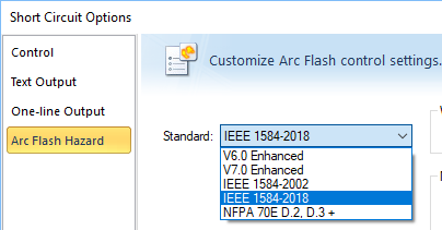
Figure 1: Arc Flash Standard Name Changes
When the IEEE 1584-2018 standard is selected, the options for user-specified worst case arcing current are removed as this value is calculated based on system parameters with the new standard. The calculated arc flash method defaults to Integrated for new databases. In addition, there are now separate working distances for switchgear in the Enclosed table. This enables you to specify a working distance for switchgear that is different from the other equipment types.
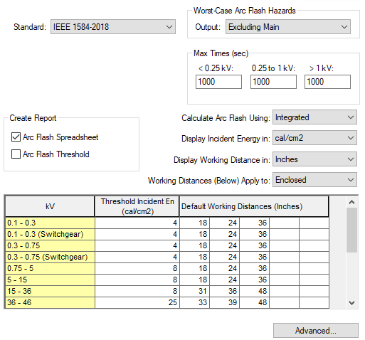
Figure 2: Arc Flash Option Changes
Advanced Arc Flash Options
In the Advanced Arc Flash Options dialog box, there are a number of changes to address updates in the IEEE 1584-2018 standard. The dialog box has been reconfigured to better display the available options.
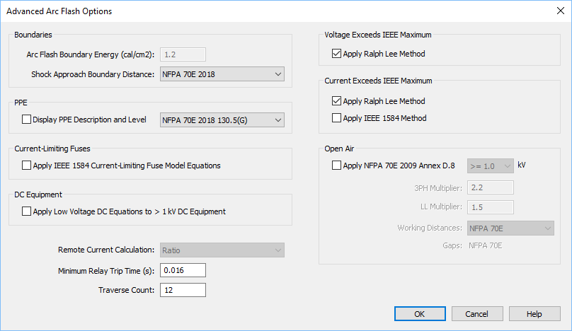
Figure 3: Advanced Arc Flash Options
- For the IEEE 1584-2018 standard, the Arc Flash Boundary Energy is set to 1.2 (cal/cm2). The Remote Current Calculation setting uses the Ratio method. These options are still available to prior methods.
- For the IEEE 1584-2018 standard, Apply IEEE 1584 Current-Limiting Fuse Model Equations only apply where electrode configuration is VCB.
- There is a new option to select what happens when voltage exceeds the limit of the IEEE 1584 model range.
- For arc flash standard IEEE 1584-2018, this setting defaults to the Ralph Lee method or can be cleared to omit calculations.
- For arc flash standards based on IEEE 1584-2002, this setting is set to the Ralph Lee method.
- For arc flash standard NFPA 70E D.2 D.3, this setting is not applicable.
- There is a new option to select what happens when bolted fault currents exceed the limit of the IEEE 1584 model range.
- For arc flash standard IEEE 1584-2018, this setting defaults to the Ralph Lee method. It can be changed to IEEE 1584 or cleared to omit calculations.
- For arc flash standards based on IEEE 1584-2002, this setting is set to IEEE 1584.
- For arc flash standard NFPA 70E D.2 D.3, this setting is not applicable.
- For open air equipment, you can choose whether to apply the NFPA 70E 2009 Annex D.8 standard. You can select whether to apply that standard to greater than or equal to 1 kV, or greater than 15 kV.
Arc Flash Hazard Tab Updates
The Arc Flash Hazard tab that appears in automatic transfer switches, buses, tool points of connection, MCCs, and panels have all been updated with new parameters to accommodate the IEEE 1584-2018 calculations. The new fields include Electrode Gap, Electrode Configuration, and Enclosure Size. You can use the defaults from the device library, or you can select to use your own user-specified values. You can customize the library defaults by voltage and equipment type.
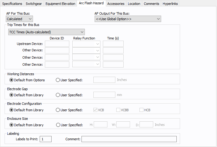
Figure 4: Arc Flash Hazard Tab
The electrode configuration, enclosure sizes, and electrode gap can be included as variables on custom arc flash labels. See Inserting a Variable from the Arc Flash Hazard Report for information on how to insert variables in custom labels.
Electrode Configurations
The new standard introduces new electrode configurations for arc flash hazard analysis. These include:
Electrodes in Enclosures:
- VCB: Vertical electrodes inside an enclosure.
- VCBB: Vertical electrodes terminating in an insulating barrier inside an enclosure.
- HCB: Horizontal electrodes inside an enclosure.
Electrodes in Open Air:
- VOA: Vertical electrodes in open air.
- HOA: Horizontal electrodes in open air.
You can specify the electrode configuration on the various equipment where arc flash hazard can be calculated. See Arc Flash Hazard Tab Updates.
For older EasyPower databases that are opened in the 10.2 version of the program, the electrode configurations are upgraded as shown in the table below.
|
Original Orientation |
New Electrode Configuration |
|---|---|
|
Vertical |
Default from Library |
|
Horizontal |
User Specified - HCB |
|
Vertical Into Barrier |
User Specified - VCBB |
|
Open Air |
Default from Library |
Electrode configurations are only applicable to the IEEE 1584-2018 standard. See Electrode Configuration for more information.
Device Library Updates
The device library has been updated to represent the new IEEE 1584-2018 standard. There are now separate tables for NEMA/ANSI and IEC rather than separate columns in the same table. There are now separate tables for IEEE 1584-2018, IEEE 1584-2002, and V7.0 Enhanced.
The library now includes columns for electrode configuration and enclosure sizes, and the library data has been expanded to include standard gap and enclosure information. You can customize the library defaults by voltage and equipment type. The voltage range that was previously from 0.2 to 1.0 has been split into 0.201 - 0.600 and 0.601 - 0.999.
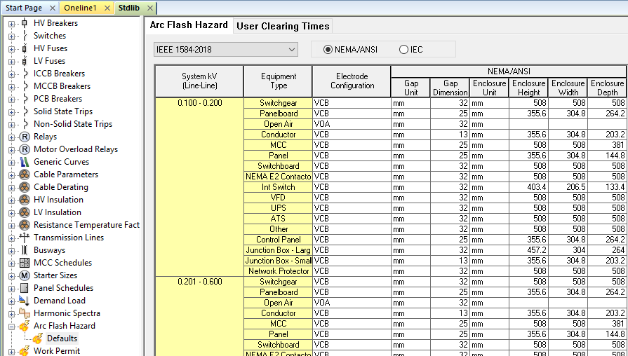
Figure 5: Arc Flash Hazard Defaults in the Device Library
You can specify more than one electrode configuration in the library, if needed. For the IEEE 1584-2018 standard the program determines the highest incident energy based on the existing electrode configurations when calculating the arc flash hazard.
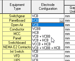
Figure 6: Multiple Electrode Configurations
Upgrading the Device Library
As of EasyPower 10.2, the Arc Flash Hazard Defaults tables in the device library now include a new table for IEEE 1584-2018. As a result of this change, EasyPower displays a warning if you open a one-line database that is connected to a device library for a version prior to EasyPower 10.2.
You can still open the database file using the older device library, but if there are default values that are not defined in the older library, EasyPower uses the program default values.
You can upgrade an older device library by opening it in EasyPower 10.2. The device library files for versions prior to 10.2 are upgraded as follows:
- The V.7 Enhanced table is retained.
- The existing IEEE 1584 table is renamed to IEEE 1584-2002.
- A new IEEE 1584-2018 table is created.
Arc Flash Hazard/Scenario Comparison Report Changes
The Arc Flash Hazard and Arc Flash Scenario Comparison Reports have new columns, including:
- Electrode Configuration
- Enclosure Height
- Enclosure Width
- Enclosure Depth
- PPE Level
- PPE Description
- Comments
The following columns have been renamed:
|
Original Name |
New Name |
Notes |
|---|---|---|
|
Arc Gap |
Electrode Gap |
The gap can come from the library or be specified on the item. The unit is always shown in millimeters. |
|
Required Clothing Description
Comments |
PPE / Comments |
In prior releases, the column text changed depending on whether PPE level was selected to be shown in the Arc Flash Hazard Options. This column retains its dual nature as in earlier releases but now both names appear in the heading. The column remains available for older databases but has been replaced with the new separate columns for PPE Level and Comments. |
|
Label Comment |
Equipment Label Comment |
|
|
Labels to Print |
Equipment Label Quantity |
|
|
Device Comment |
Device Label Comment |
|
|
Device Comment Count |
Device Label Quantity |
|
For the new IEEE 1584-2018 calculations, the arc flash results in the Arc Flash Hazard report that are derived using the reduced arcing current are displayed in pink text, similar to how the worst-case arcing current has been displayed on the report in the past.
The pink text means the maximum incident energy was calculated using the reduced arc current. The black text means the maximum incident energy was calculated by using the average arc current in the IEEE 1584-2018 standard.
As with previous releases, blue text indicates the cell can be edited, and the calculations will be updated using the new values.
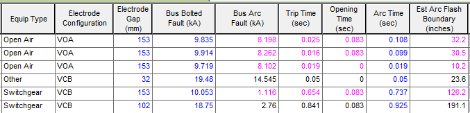
Figure 7: Colored Text in the Arc Flash Hazard Report
The default columns on the reports change based on the arc flash standard selected, so that columns that are not applicable to the selected standard do not appear.
Work Task Changes
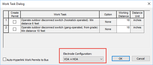
The Work Task Dialog now has an option to select from one or multiple electrode configurations.
Database Browser and Database Report Changes
There are new columns in the Database Browser and Database Report for:
- Electrode Configuration
- Enclosure Height
- Enclosure Width
- Enclosure Depth
In addition, the following columns have been renamed:
|
Original Name |
New Name |
Notes |
|---|---|---|
|
Forced WD |
Working Distance Setting |
Displays either "Default" or "Specified." |
|
WD Value |
Working Distance |
If the equipment's working distance is user-specified, the report displays the user-specified value. Otherwise it will show the value as retrieved from the first column of the table in Short Circuit Options > Arc Flash Hazard, based on the equipment voltage and equipment type. Note that there are two tables: one for open air and one for enclosed. Units are based on the setting in Options > System. |
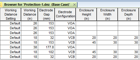
Figure 8: New Columns in the Database Browser
Panel Row Behavior Changes
We have made changes to the way that panel rows work. The cells for the load values for the A, B and C phases are now arranged diagonally and we have modified what happens when you insert and delete rows.
Phases and Poles
The phases and number of poles for the circuit affect the panel row behavior. Below is an image of a three-phase panel with a mixture of poles. The phases appear diagonally for each row, with phase A in the first row in the first column, phase B in the second row in the second column, and phase C in the third row in the third column. This phase pattern repeats throughout the spreadsheet.
The number of poles indicates how the rows are grouped together to make up a circuit. For example, rows 13-17 are grouped because the number of poles is set to 3. Rows 19-21 are grouped together because the number of poles is set to 2. The remaining rows are all individual because the poles are set to 1.
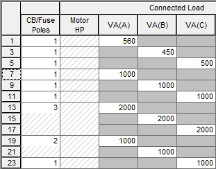
Figure 9: Panel Rows in 3 Phase (Detailed View)
As a result of this change, the behavior when inserting, deleting, or moving rows has changed. You can also clear a panel row without removing it. See Panel Row Behaviors for details.
We have also changed the behavior when you change the number of poles on a circuit row. Now, all affected rows have their VA/Amps values cleared when the number of poles is changed. An exception to this is when the load type is motor. In that instance, the VA/Amp values are recalculated based on the HP or kW value.
In panels that have a multi-pole circuit that is a Load Type of Sub-Panel, all VA/Amp cells are now unavailable for entry.
Also, if you change the number of poles at the bottom of a panel spreadsheet and there are not enough rows for the number selected, you will receive a warning to enter a valid number for the rows available.
Phases in the Same Row
Note that in versions of EasyPower prior to 10.2, it was possible to enter the load values on the same row. EasyPower allowed this and interpreted the values in the appropriate phases. Beginning with version 10.2, the values need to be put into the correct phase. If you open an older database and look at the panel schedule, you may find values in the same row in red. To correct this, simply delete the red text and type the value into the proper row.
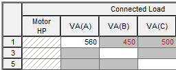
Figure 10: Load Values in Incorrect Phases
See Panel Row Behaviors for details.
Simplified View Changes
The name of the View on the Description tab of the Panel data dialog has changed from Simplified - 3 Phase to Simplified.
You can now enter load values in the VA and Breaker Amps columns in the Simplified view, and the load value you enter is automatically added to the proper phase.
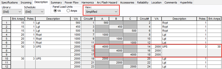
Figure 11: Simplified View Improvements
Additional Enhancements
- Grounding in 3-Phase Motors: For 3-phase motors where the motor type is induction, synchronous, or synchronous condenser, there is now the ability to select a connection type of D, Y, or YG (delta, wye, or wye-ground). There are new grounding fields on the Short Circuit tab including X0v (saturated zero sequence reactance in percent), R (neutral ground resistance in ohms), jX (neutral ground reactance in ohms), and Amp Class. See Motor Data for more information.
- Grounded Motor Symbol: When the motor connection is set to YG, a new symbol is displayed on the one-line to indicate a grounded motor. The symbol may also include a grounding reactor or resistor symbol. See Motor Type for more information.
- Zoom Levels: When you use Find-Select to find an item on the one-line, if your current zoom level is less than 90%, the selected item (or last selected item if you used Additive Select) is centered in the window and the one-line is zoomed to 100%. If the zoom level is already more than 90%, the zoom level remains unchanged.
- Transient Motor Starting: Previously, when the Transient Motor Starting module was purchased without the Dynamic Stability features, the text for some of the windows and menus referred to Dynamic Stability instead of Transient Motor Starting. The text now correctly reflects Transient Motor Starting when that is the module purchased.
- Tabbed Interface: The EasyPower session window now has a tabbed interface available. This enables you to select between different tabs to switch between the one-line view and your reports, for example. See General Tab for more information.
- Deactivated Equipment: We now provide additional feedback if you deactivate a bus that is connected to active equipment. You are now asked if you also want to deactivate the connected equipment.
Bug Fixes
- Fixed an issue where Data Text Visibility did not refresh after it was changed. For example, changing the text visibility to "Always Hide" did not actually hide text on the one-line.
- Fixed an issue where the note font on a TCC printout was too small to read.
- Fixed an issue where drawings exported to DXF did not show the direction arrows for current.
- Fixed an issue where the default motor service factor was being set incorrectly to 0 instead of to the default value.
- Fixed an issue where it was not possible to move the "To" end of a cables, busways, or transmission lines when connected in parallel.
- Fixed an issue where arc flash results in the Scenario Comparison report did not match the results in the scenario due to incorrect unit conversions.
- Fixed an issue where the integrated method was reporting upstream devices that were not relevant to the faulted bus.
More Information
| What's New - EasyPower 10.2 | 10.2 SP1 Release Notes |
|
|