Panel - Summary Tab
The summary tab sums all the connected loads and displays results for total connected, demand, code factor and design. There are two sections in this summary: Panel Load and Including Downstream Load.
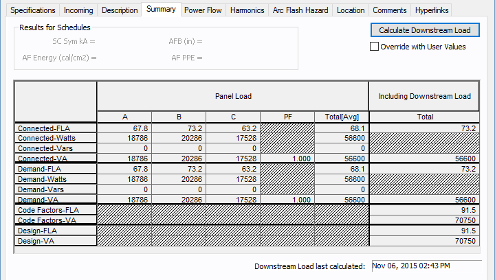
Figure 1: Summary Tab
| Option | Description |
|---|---|
|
Calculate Downstream Load
|
Calculates the total load on the panel, taking into account the connected load, demand factors, and NEC code factors. Single-Phase Load Calculations: Load calculations for 1PH equipment follow the conventional load calculation method similar to 3PH systems. The only difference is that the current values are specific to 1PH and the equipment voltage. At any distribution point (such as a bus, panel, or MCC.), the apparent power (VA or kVA) is summed up first for each energized (hot or live) current-carrying conductor. The respective load current is calculated from the voltage for the line of circuit. For each branch circuit tapped off at the distribution point, the program keeps track of the phase connection type. For example, phase connection for 1PH branches could be AN, BN, CN, AB, BC or CA. During load calculations, downstream load values are applied to the correct phases at the upstream distribution point. The results are displayed under the column Downstream Load in the Summary tab of the Panel Data dialog box and in the Switchgear, Panelboard, or Switchboard tab of the Bus Data dialog box. |
|
Override with User Values |
This check box enables you to enter your own data. You can enter measured data or assumed data in the available fields. If this check box is not enabled, then the program calculates all the downstream loads and displays the total. For this feature to work, it is necessary to have a source upstream to the panel. This feature is applicable only to radial distribution systems. Downstream branches with any power source are not accounted for. |
Panel Load
This summarizes the loads fed directly from this panel. It does not include loads fed through downstream sub-panels. These are not user-definable fields. They are updated automatically when you make changes in the spreadsheet of the Description tab. The watts and vars shown in this table do not reflect the downstream load of the sub-panels.
Note: Your phase descriptions may be different than described here if they have been customized in Tools > Options > Terminology.
| Option | Description |
|---|---|
|
Connected W (A phase): |
Total of the |
|
Connected VAR (A phase): |
Total of the |
|
Connected W (B phase): |
Total of the |
|
Connected VAR (B phase): |
Total of the |
|
Connected W (C phase): |
Total of the |
|
Connected VAR (C phase): |
Total of the |
|
Demand W (A phase): |
Total of the |
|
Demand VAR (A phase): |
Total of the |
|
Demand W (B phase): |
Total of the |
|
Demand VAR (B phase): |
Total of the |
|
Demand W (C phase): |
Total of the |
|
Demand VAR (C phase): |
Total of the |
 of (VAA * PF)
 of (VA2A - W2A)1/2
  of (VAB * PF)
 of (VA2B - W2B)1/2
  of (VAC * PF)
 of (VA2C - W2C)1/2
  of (VAA * PF) * DF
 of (VA2A - W2A)1/2 * DF
 of (VAB * PF) * DF
 of (VA2B - W2B)1/2 * DF
 of (VAC * PF) * DF
 of (VA2C - W2C)1/2 * DF
| Option | Description |
|---|---|
|
Including Downstream Load |
Loads connected through downstream sub-panels and buses are summarized in this section. |
More Information
- Panel Data
- Database Dialog Box Toolbar
- Panel - Connection Information
- Panel - Specifications Tab
- Panel - Incoming Tab
- Panel - Description Tab
- Panel - Power Flow Tab
- Panel - Harmonics Tab
- Panel - Arc Flash Hazard Tab
- Panel - Accessories Tab
- Panel - Reliability Tab
- Panel - Location Tab
- Panel - Comments Tab
- Panel - Hyperlinks Tab
- Panel - Collected Data Tab
- Panel - Media Gallery Tab