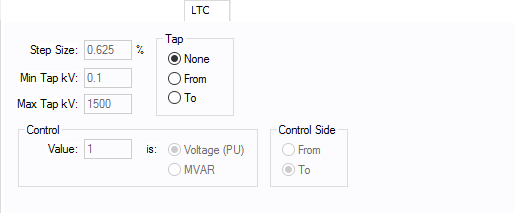
Figure 1: LTC Tab
| Option | Description |
|---|---|
|
Load tap changer (LTC) position can be placed on either side of the transformer by selecting From or To. If the transformer does not have an LTC, select None for standard fixed taps. Fixed off-nominal taps can be entered in the main dialog's Tap kV field. |
|
|
Step Size |
The default is 0.625 but you can type in your own percentage step size both here and in the power flow two-winding transformer temporary dialog box. |
|
Min Tap kV |
Minimum tap kV, which is used to determine the bottom limit that the tap can be adjusted to during a power flow analysis. This value should be the lowest tap on the transformer to get meaningful results. The default of 0.1 kV is not realistic and should be changed to the actual values if the LTC is used. |
|
Max Tap kV |
Maximum tap kV, which is used to determine the upper limit that the tap can be adjusted to during a power flow analysis. This value should be the highest tap on the transformer to get meaningful results. The default of 1500 kV is not realistic and should be changed to the actual values if the LTC is used. |
|
Control Value |
: Control value, which is determined by the Control Type field.
|
|
Control Type |
Determines how the LTC model is used.
|
|
Control Side |
The LTC can control the voltage or MVAR on either side of the transformer, regardless of which side the tap is located. |
More Information
- Two Winding Transformer Data
- Database Dialog Box Toolbar
- Two Winding Transformer - Connection Information
- Two Winding Transformer - Specifications Tab
- Two Winding Transformer - Impedance Tab
- Two Winding Transformer - TCC Tab
- Two Winding Transformer - Harmonics Tab
- Two Winding Transformer - Stability Tab
- Two Winding Transformer - Reliability Tab
- Two Winding Transformer - Location Tab
- Two Winding Transformer - Comments Tab
- Two Winding Transformer - Hyperlinks Tab
- Two Winding Transformer - Collected Data Tab
- Two Winding Transformer - Media Gallery Tab
