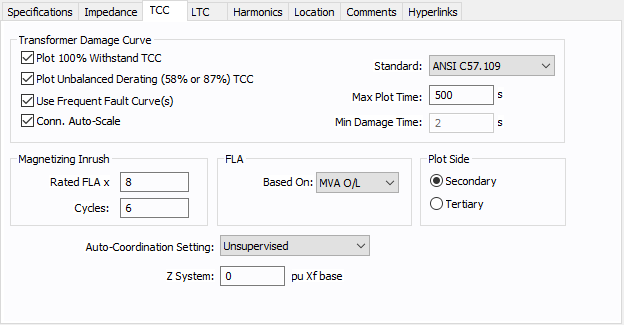
Figure 1: TCC Tab for the Transformer Data Dialog Box
| Option | Description |
|---|---|
|
Select this check box to plot transformer damage curve for 100% withstand. This is without taking into consideration the derating factor for winding connection type and the type of fault. |
|
|
Select this check box to plot transformer damage curve taking into consideration the derating factor for winding connection type and the type of fault. The transformer curve shifts left by 58% or 87% depending on the connection type. |
|
|
Use Frequent Fault Curve(s) |
Select this check box to plot the transformer damage curves as Category II to IV (thermal and mechanical withstand) for frequently occurring faults. The curve shifts towards the left depending upon the transformer impedance. |
|
Conn. Auto-Scale |
When this check box is selected, the program automatically scales the TCC curves based on the phase connection type. Traditionally, for 3PH curves in a TCC, scaling the curves based on the reference voltage is adequate. If a line-to-neutral connected 1PH device is to be plotted with an upstream 3PH device, then the LN connected 1PH curve needs to be shifted by a factor of the SQRT(3) in addition to the voltage-based scaling. Similarly, if a line-to-neutral connected 1PH device is to be plotted with an upstream 1PH-3W device, then the LN connected 1PH curve needs to be shifted by a factor of the 2 in addition to the voltage-based scaling. When the check box is not selected, scaling based on the phase connection type is not applied. The check box status for individually stored TCC plots can be different. The default for new TCC plots is obtained from the database for the device. |
|
Standard |
The standard according to which the curve is plotted. |
|
Maximum Plot Time |
The maximum time in seconds for which the transformer damage curve is plotted. |
|
Minimum Damage Time |
When the IEC 76-5.4 standard is selected, the thermal ability of the transformer to withstand short circuit is plotted for the time specified here. The default is 2 seconds. |
|
FLA x |
Magnetizing inrush current as multiples of full load amps for the primary winding. |
|
Cycles |
Time taken by magnetizing inrush current in terms of number of cycles. |
|
FLA Based on |
Calculation basis for full load amps. “MVA O/L” is the MVA capacity for overload and “Rated MVA” is the self-cooled capacity. |
|
Plot Side |
(Three-winding transformer only) The side of transformer for which the short circuit withstand is plotted. Short circuit is applied on Secondary or Tertiary side. The primary line current is shown in the plot. |
|
Auto-Coordination Setting |
Specify whether the protective device is accessible only to qualified personnel (supervised) or unsupervised. This affects the protective device settings based on NEC rules. |
|
Z System |
While plotting the transformer damage curve, typical practice assumes infinite source (zero system impedance) on the upstream side of the transformer. You can include the upstream system impedance to lower the maximum fault current that the transformer sees. The system impedance must be converted to per unit impedance on the transformer MVA base. |
More Information
- Two Winding Transformer Data
- Database Dialog Box Toolbar
- Two Winding Transformer - Connection Information
- Two Winding Transformer - Specifications Tab
- Two Winding Transformer - Impedance Tab
- Two Winding Transformer - LTC (Load Tap Changer) Tab
- Two Winding Transformer - Harmonics Tab
- Two Winding Transformer - Stability Tab
- Two Winding Transformer - Reliability Tab
- Two Winding Transformer - Location Tab
- Two Winding Transformer - Comments Tab
- Two Winding Transformer - Hyperlinks Tab
- Two Winding Transformer - Collected Data Tab
- Two Winding Transformer - Media Gallery Tab
