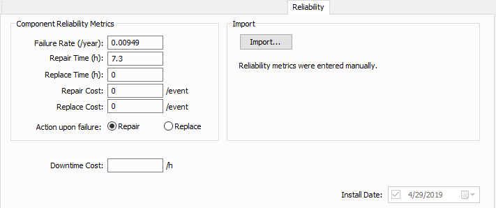
This tab appears when your EasyPower license includes the optional Reliability feature and the component is included in reliability analysis. Use this tab to track reliability data on your system components. The reliability features are based on IEEE Standard 493-2007. Refer to the standard for additional information.
Note: Rectifiers, inverters, and AFDs are treated as single nodes (branches) and their reliability data applies directly to them. These can become dependent first-order cut sets if connected to first-order buses.

Figure 1: Reliability Tab
| Option | Description |
|---|---|
|
Import |
Click Import to import reliability data from the selected library, class, and category into the reliability data fields. After you import, the imported values appear below the Import button.
Note: You can also import reliability data for all components in the one-line at the same time. See Importing Reliability Data for more information. |
|
Failure Rate |
The calculated rate of failure for the component on a yearly basis. If you have imported library data, the imported value is displayed here. You can manually type a value to have the program use that value instead. Note: For cables, transmission lines, and busway, this value is per unit of length. |
|
Repair Time |
The mean average time to repair the component, expressed in hours. If you have imported library data, the imported value is displayed here. You can manually type a value to have the program use that value instead. Note: For cables, transmission lines, and busway, this value is per unit of length. |
|
Replace Time |
The mean average time to replace the component, expressed in hours. If you have imported library data, the imported value is displayed here. You can manually type a value to have the program use that value instead. Note: For cables, transmission lines, and busway, this value is per unit of length. |
|
Repair Cost |
The estimated cost to repair the component. This value is not used if the Action upon failure is set to Replace. |
|
Replace Cost |
The estimated cost to replace the component. This value is not used if the Action upon failure is set to Repair. |
|
Action upon failure |
The recommended action to take upon failure of the component: repair or replace. |
|
Downtime Costs |
The downtime cost for the individual piece of equipment. This is available for a bus, MCC, panel, motor, or load. |
|
SC Failure Mode (%) |
This is an adjustable percentage that is applied to the failure rate of indirect protective devices and represents the percentage of total failures in each failure mode. For circuit breakers, the default is 9%. For switches, the default is 0% (no reliability). |
|
Install Date |
This option is reserved for future use. |
More Information
- Two Winding Transformer Data
- Database Dialog Box Toolbar
- Two Winding Transformer - Connection Information
- Two Winding Transformer - Specifications Tab
- Two Winding Transformer - Impedance Tab
- Two Winding Transformer - TCC Tab
- Two Winding Transformer - LTC (Load Tap Changer) Tab
- Two Winding Transformer - Harmonics Tab
- Two Winding Transformer - Stability Tab
- Two Winding Transformer - Location Tab
- Two Winding Transformer - Comments Tab
- Two Winding Transformer - Hyperlinks Tab
- Two Winding Transformer - Collected Data Tab
- Two Winding Transformer - Media Gallery Tab
